Vehicle-mounted charging pile for new energy vehicle

A new energy vehicle, on-board charging technology, applied in the direction of electric vehicle charging technology, charging stations, electric vehicles, etc., can solve the problems of not being stable enough, not convenient enough to follow the vehicle movement, etc., to achieve easy opening and closing, increase protection effect, increase The effect of stability

Pending Publication Date: 2021-11-02
无锡龙创汽车技术有限公司
View PDF1 Cites 0 Cited by
  • Summary
  • Abstract
  • Description
  • Claims
  • Application Information

AI Technical Summary

Problems solved by technology

[0003] In the prior art, a Chinese patent document with the authorized announcement number CN201520431927.0 describes a mobile non-vehicle charging pile. The output power is relatively large, the charging efficiency is high, there is no external charging cable, it is easy to move and transport, and it can widely provide convenient charging services for various electric vehicles in non-fixed places. However, it is not suitable for vehicle charging, which is not enough It is stable and not convenient enough to follow the vehicle, which has brought some adverse effects on people's use. Therefore, we propose a new energy vehicle with a vehicle-mounted charging pile

Method used


Image

  • Vehicle-mounted charging pile for new energy vehicle
  • Vehicle-mounted charging pile for new energy vehicle
  • Vehicle-mounted charging pile for new energy vehicle

Examples


specific Embodiment 1

[0031] This embodiment is a vehicle-mounted charging pile for new energy vehicles.

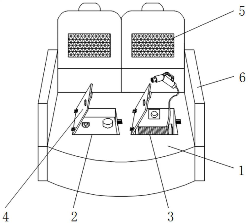
[0032] Such as Figure 1-5 Shown, comprise automobile trunk floor 1, the left side of automobile trunk floor 1 upper end outer surface is provided with first storage chamber 2, and the right side of automobile trunk floor 1 upper end outer surface is provided with second storage chamber 3, the first A protective mechanism 4 is arranged between the storage chamber 2, the second storage chamber 3, and the trunk floor 1 of the automobile. Side panels 6 are fixedly installed on both sides of the outer surface of the upper end of the trunk floor 1 of the automobile. A seat 5 is fixedly installed on the outer surface of the end.

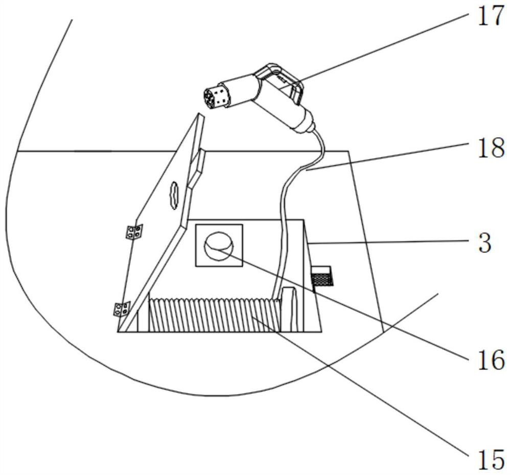
[0033]The inside of the first storage chamber 2 is provided with a charging pile body 7, the outer surface of the lower end of the charging pile body 7 is fixedly equipped with a buffer mechanism 19, the inside of the second storage chamber 3 is fixedly installed with a w...

specific Embodiment 2

[0036] This embodiment is an embodiment of the protection mechanism 4 in the on-board charging pile for new energy vehicles.

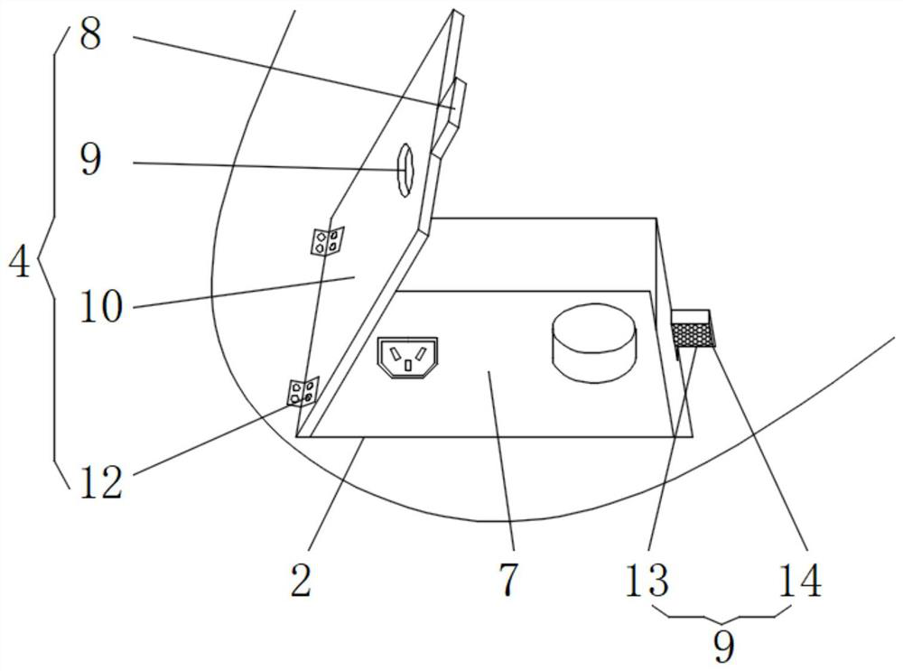
[0037] Such as figure 1 , 2 , 3, a protective mechanism 4 for a vehicle-mounted charging pile for a new energy vehicle, the protective mechanism 4 includes a limiting iron block 8, a handle 9, a protective cover 10, a hinge 12, a magnetic block 13 and a limiting groove 14 , and the handle 9 is fixedly installed on the right side of the outer surface of the upper end of the protective cover 10, one side of the outer surface of the protective cover 10 is rotatably connected with the trunk floor 1 of the automobile through the hinge 12, and the limit iron block 8 is fixedly installed on the protective cover On the outer surface of the other side of the plate 10, the limit groove 14 is opened on the right side of the second storage chamber 3 top, and the magnetic block 13 is fixedly installed in the inside of the limit groove 14; the outer wall of the lim...

specific Embodiment 3

[0039] This embodiment is an embodiment of a buffer mechanism 19 in a vehicle-mounted charging pile for a new energy vehicle.

[0040] Such as figure 1 , 4 As shown, a buffer mechanism 19 for a vehicle-mounted charging pile for a new energy vehicle, the buffer mechanism 19 includes a buffer spring 20, a slider 21, a guide rod 22, a connecting rod 23, a first connecting block 24, a second connecting block 25, The sliding hole 26, the mounting plate 27 and the concave limit rod 28, and the concave limit rod 28 are fixedly mounted on the inner walls of both sides of the first storage chamber 2, the mounting plate 27 is fixedly mounted on the outer surface of the lower end of the charging pile body 7, and the sliding hole 26 is provided on the left and right sides of the outer surface of the upper end of the mounting plate 27, the first connecting block 24 is fixedly installed on the left and right sides of the outer surface of the lower end of the mounting plate 27, the guide ro...


PUM


Abstract

The present invention discloses a vehicle-mounted charging pile for a new energy vehicle. The vehicle-mounted charging pile comprises a vehicle trunk bottom plate, a first storage cavity is formed in the left side of the outer surface of the upper end of the vehicle trunk bottom plate, and a second storage cavity is formed in the right side of the outer surface of the upper end of the vehicle trunk bottom plate; and protection mechanisms are arranged between the first storage cavity and the automobile trunk bottom plate and between the second storage cavity and the automobile trunk bottom plate correspondingly, and side surrounding plates are fixedly installed on the two sides of the outer surface of the upper end of the automobile trunk bottom plate. According to the vehicle-mounted charging pile for the new energy vehicle, the storage cavity and the protection mechanism are arranged, the safety coefficient is increased, the buffering mechanism is arranged, the stability of the charging pile body is improved, the winding mechanism is arranged, a second belt wheel is driven to rotate through operation of a forward and reverse motor, and the charging pile is more stable. Rotation of the second belt pulley drives rotation of the first belt pulley through a belt, rotation of the first belt pulley drives rotation of the winding roller through the first rotating shaft, and winding of the wire is achieved.

Description

technical field [0001] The invention relates to the technical field of charging piles for new energy vehicles, in particular to a vehicle-mounted charging pile for new energy vehicles. Background technique [0002] As the country continues to increase policy and institutional support for the new energy vehicle industry, my country's current electric vehicle industry is extremely hot, and charging piles, the charging equipment that must be used for electric vehicles, have become the main bottleneck restricting its development. At present, the charging facilities that have been put into operation or arranged in the market are mainly various fixed non-vehicle charging piles. Electric vehicles must go to various fixed locations or fixed places arranged by charging piles to complete the charging of electric vehicles. Therefore, there is an urgent need in the market A mobile charging device makes it unnecessary for an electric vehicle to drive to a fixed place every time to complete...

Claims


Application Information

Patent Timeline
IPC IPC(8): B60L53/18B65H75/42B65H75/44B60L53/31B60R7/02
CPCB60L53/18B65H75/425B65H75/4486B60L53/31B60R7/02Y02T10/70Y02T10/7072Y02T90/12Y02T90/14
Inventor 王珣唐晓东穆星
Owner 无锡龙创汽车技术有限公司
Why Eureka
Try Eureka