
Automatic communication cable laying device

A technology for cable laying and automatic communication, applied in cable laying equipment, transportation and packaging, transportation of filamentous materials, etc. The effect of laying efficiency, reducing labor intensity and avoiding offset

Inactive Publication Date: 2021-11-02
衢州忻蕊智能科技有限公司
View PDF0 Cites 3 Cited by
  • Summary
  • Abstract
  • Description
  • Claims
  • Application Information

AI Technical Summary

Problems solved by technology

[0003] The following problems exist in the laying process of the existing cables: 1. Because the weight of the cable is heavy, it often requires many people to drag it together during the laying process, which is very time-consuming and laborious; 2. The cable cannot be fixed while laying during laying, so As a result, the entire cable will often deviate from the laying track after laying, and it needs to be adjusted twice to fix it, which wastes manpower and increases the labor intensity of workers; 3. Usually, the cable roller and the laying device are independent of each other, so in During the laying process, the construction personnel need to transport the cable rollers additionally, and the cables on the cable rollers are not easy to be replaced after being used up, which relatively prolongs the length of the laying operation

Method used


Image

  • Automatic communication cable laying device
  • Automatic communication cable laying device
  • Automatic communication cable laying device

Examples


Embodiment

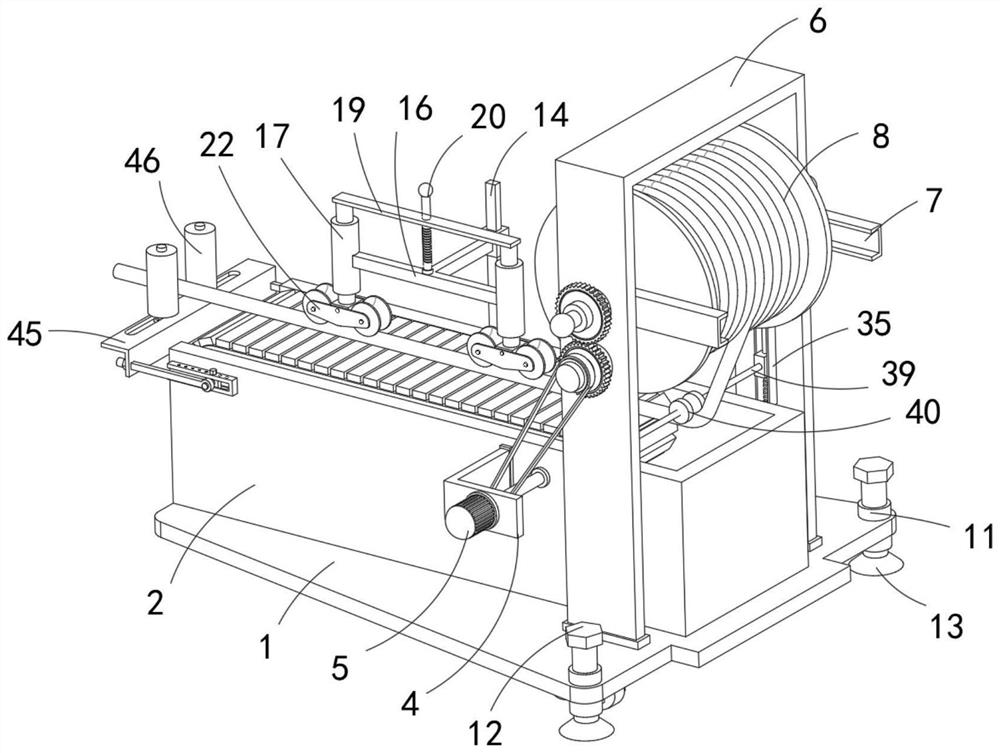
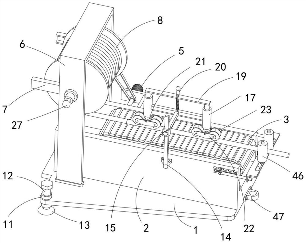
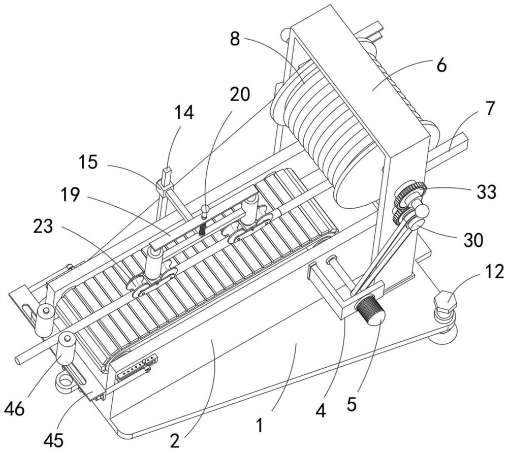
[0037] Refer Figure 1-8 An automatic communication cable laying device comprising the bottom plate 1 and the rectangular groove body 2, the rectangular groove body 2 is fixedly coupled to the upper end of the bottom plate 1, and the lower end of the bottom plate 1 is provided with a moving adjustment mechanism, and the moving adjustment mechanism includes a plurality of fixed connections on the bottom plate. 1 The lower U-shaped member 9, and the slot of the U-shaped member 9 is disposed downward, and the slot of the U-shaped member 9 is rotated and connected to the roller 10 in contact with the ground, and the upper end of the bottom plate 1 is fixedly connected with a plurality of vertical threads. The bobbin 11, and the threaded barrel 11 is threaded and attached to the vertical adjustment screw 12, and the lower end of the adjustment screw 12 extends to the lower side of the threaded tube 11 and fixed to the support 13 in contact with the ground, specifically L The bottom plat...


PUM


Abstract

The invention belongs to the technical field of communication cables, and particularly relates to an automatic communication cable laying device. The automatic communication cable laying device comprises a bottom plate and a rectangular groove body, the rectangular groove body is fixedly connected to the upper end of the bottom plate, a movement adjusting mechanism is arranged at the lower end of the bottom plate, a rectangular through groove penetrating through the side wall of the rectangular groove body is formed in the upper end of the rectangular groove body, a belt conveyor used for conveying a cable is arranged in the rectangular through groove, an L-shaped support is fixedly connected to the side wall of the rectangular groove body, a driving motor used for driving the belt conveyor is fixedly connected to the outer side wall of the L-shaped support, a pressing and guiding mechanism used for assisting in conveying the cable is arranged on the side wall of the rectangular groove body, and the pressing and guiding mechanism is correspondingly connected to the upper end of the cable and is arranged opposite to the belt conveyor. According to the automatic communication cable laying device, the cable is paid off and conveyed through the driving motor and a transmission mechanism, so that the laying efficiency is improved, meanwhile, the labor intensity of workers can be reduced, and manpower waste is avoided.

Description

Technical field [0001] The present invention relates to the technical field of communication cables, and more particularly to an automatic communication cable laying device. Background technique [0002] Communication cable laying refers to the process of installing cables along a routing of the survey to form a cable line. According to the occasion, several laying methods such as overhead, underground, water, walls, and tunnels can be divided. The laying method of reasonable selection cable is important to ensure the quality, reliability and construction maintenance of the line. [0003] Existing cables have the following problems in the layout of the cable: After the entire cable is laid, it will often deviate from the laying track, and it is necessary to carry out the secondary adjustment in fixed, the labor intensity of the workers; three, usually the cable roller and the laying device are independent of each other, so The construction personnel need to transport the cable ro...

Claims


Application Information

Patent Timeline
Patent Type & Authority Applications(China)
IPC IPC(8): B65H49/34B65H57/14B65H51/14B65H57/26B65H67/02H02G1/06
CPCB65H49/34B65H57/14B65H51/14B65H57/26B65H67/02H02G1/06B65H2701/34
Inventor 李小龙
Owner 衢州忻蕊智能科技有限公司
Learn More