
Rapid rectification system for waste oil regeneration

A rectification system and waste oil regeneration technology, which is applied in the petroleum industry, hydrocarbon oil treatment, and multi-stage serial refining process treatment. Damage, unable to install the agitator and other problems, to achieve the effect of low production cost, high power consumption and convenient operation

Pending Publication Date: 2021-11-02
CHONGQING FANGSHENG CLEANING EQUIP CO LTD
View PDF0 Cites 0 Cited by
  • Summary
  • Abstract
  • Description
  • Claims
  • Application Information

AI Technical Summary

Problems solved by technology

Our company has been engaged in the research and development and production of waste oil regeneration equipment for a long time. We have a large number of independent intellectual property rights in waste oil regeneration technology. In terms of waste oil regeneration and distillation, on 2015-05-27, our company applied for the System", patent application number 2015102771925; 2017-12-15, the company applied for "waste oil regeneration high-temperature distillation catalytic device", patent application number 201711345996X; 2017-12-15, the company applied for "waste oil regeneration rectification complete set Device" patent application number 2017113457625; in these waste oil rectification technical schemes, the heating is carried out by electric heating with built-in horizontal or vertical electric heating tubes, and the electric heating tubes occupy part of the space in the tank, and the tank also The agitator cannot be installed. At the same time, the inner wall of the tank and the electric heating tube will also be scaled. The electric heating tube is easily damaged. The device for oil rectification also needs further optimization

Method used


Image

  • Rapid rectification system for waste oil regeneration
  • Rapid rectification system for waste oil regeneration
  • Rapid rectification system for waste oil regeneration

Examples


Embodiment 1

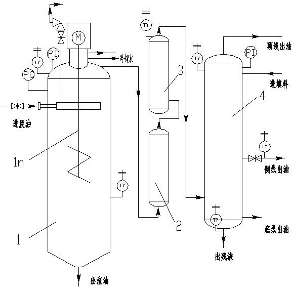
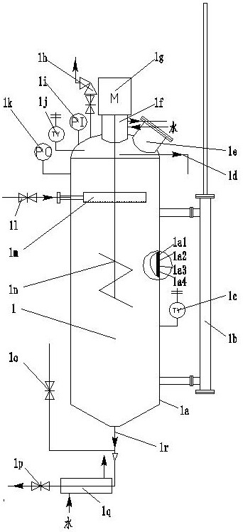
[0028] refer to figure 1 , figure 2 , image 3 , Figure 4 , Figure 5 , Figure 6 , Figure 7 , Figure 8 , Figure 9 , a waste oil regeneration fast rectification system, the system uses pipes, pipe fittings, and valves to connect the reactor tank 1, adsorption tower 2, catalytic tower 3, and fractionation tower 4 in series; the waste oil enters from the oil inlet pipe valve 1l Reactor tank 1, then through adsorption tower 2, catalytic tower 3, fractionation tower 4, and finally the regenerated light oil produced by rectification is discharged from the top line oil outlet 4p of catalytic tower 3, and the light regenerated base oil produced by rectification Discharge from catalytic tower 3 side line oil outlet 4r, the heavy regeneration base oil that rectification produces is discharged from the bottom oil outlet 4a of catalytic tower 3; Described reactor 1 adopts electromagnetic heating, and the power of electromagnetic heating is 60-180Kw; The reactor tank body 1a ...

Embodiment 2

[0030] refer to figure 1 , figure 2 , image 3 , Figure 4 , Figure 5 , Figure 6 , Figure 7 , Figure 8 , Figure 9 , a waste oil regeneration fast rectification system, the system uses pipes, pipe fittings, and valves to connect the reactor tank 1, adsorption tower 2, catalytic tower 3, and fractionation tower 4 in series; the waste oil enters from the oil inlet pipe valve 1l Reactor tank 1, then through adsorption tower 2, catalytic tower 3, fractionation tower 4, and finally the regenerated light oil produced by rectification is discharged from the top line oil outlet 4p of catalytic tower 3, and the light regenerated base oil produced by rectification Discharge from catalytic tower 3 side line oil outlet 4r, the heavy regeneration base oil that rectification produces is discharged from the bottom oil outlet 4a of catalytic tower 3; Described reactor 1 adopts electromagnetic heating, and the power of electromagnetic heating is 60-180Kw; The reactor tank body 1a ...

Embodiment 3

[0032] refer to figure 1 , figure 2 , image 3 , Figure 4 , Figure 5 , Figure 6 , Figure 7 , Figure 8 , Figure 9 , a waste oil regeneration fast rectification system, the system uses pipes, pipe fittings, and valves to connect the reactor tank 1, adsorption tower 2, catalytic tower 3, and fractionation tower 4 in series; the waste oil enters from the oil inlet pipe valve 1l Reactor tank 1, then through adsorption tower 2, catalytic tower 3, fractionation tower 4, and finally the regenerated light oil produced by rectification is discharged from the top line oil outlet 4p of catalytic tower 3, and the light regenerated base oil produced by rectification Discharge from catalytic tower 3 side line oil outlet 4r, the heavy regeneration base oil that rectification produces is discharged from the bottom oil outlet 4a of catalytic tower 3; Described reactor 1 adopts electromagnetic heating, and the power of electromagnetic heating is 60-180Kw; The reactor tank body 1a ...


PUM

PropertyMeasurementUnit
thicknessaaaaaaaaaa
heightaaaaaaaaaa
diameteraaaaaaaaaa

Abstract

The invention discloses a rapid rectification system for waste oil regeneration, and relates to a waste oil regeneration rectification device. The system is formed by sequentially connecting a reaction kettle tank body, an adsorption tower, a catalysis tower and a fractionating tower in series through pipes, pipe fittings and valves; waste oil enters the reaction kettle tank body from an oil inlet pipe valve and then passes through the adsorption tower, the catalysis tower and the fractionating tower, and finally regenerated light oil generated by rectification is discharged from a top line oil outlet of the catalysis tower; light regenerated base oil generated by rectification is discharged from a side line oil outlet of the catalysis tower, and heavy regenerated base oil generated by rectification is discharged from a bottom oil outlet of the catalysis tower; the electromagnetic heating power of the reaction kettle is 60-180Kw; and the reaction kettle tank body is a vertical cylindrical tank body. The system is scientific and reasonable in structure, the stirrer is arranged in the reaction kettle tank body, the electromagnetic heating device never scales, the power consumption is only half of that of an original device, and the consumed time is about 65% of the consumed time of waste oil regeneration rectification of the original device; the production cost of waste oil regeneration is low; the quality of regenerated and rectified oil is good; and operation is convenient, and popularization value is achieved.

Description

technical field [0001] The invention relates to a waste oil regeneration rectification device, and more particularly relates to a waste oil regeneration fast rectification system. Background technique [0002] Waste oil means that after the oil has been used for a period of time, due to the immersion of pollution impurities and the oxidative deterioration of some components, the oil that cannot be used and replaced is collectively referred to as waste oil. Waste oil mainly includes waste engine oil, waste hydraulic oil, waste cutting oil, waste cold rolling oil, etc., as well as waste mineral oil produced in the automobile industry, mechanical processing industry, equipment manufacturing and other industries. The total amount of harmful impurities in waste oil is usually in the range of 5% to 35%, and the remaining 95% to 65% are oil components. Appropriate processes are adopted to purify and regenerate the waste oil. The quality of the treated waste oil is It is able to ap...

Claims


Application Information

Patent Timeline
Patent Type & Authority Applications(China)
IPC IPC(8): C10G53/08
CPCC10G53/08C10G2300/1007
Inventor 豆远奎
Owner CHONGQING FANGSHENG CLEANING EQUIP CO LTD
Learn More