MOCVD system reaction cavity cleaning device

A technology for cleaning devices and reaction chambers, applied in the directions from chemically reactive gases, gaseous chemical plating, crystal growth, etc., can solve the problems of long growth cycle of epitaxial products, decreased production capacity, unstable process results, etc.

Pending Publication Date: 2021-11-02
苏州耘林芯半导体科技有限公司
View PDF0 Cites 0 Cited by
  • Summary
  • Abstract
  • Description
  • Claims
  • Application Information

AI Technical Summary

Problems solved by technology

In order to grow compound semiconductor materials with uniform components, ultra-thin layers, and heterogeneous structures, some residual substances will appear in the reaction chamber during the working process. These substances generally need to be cleaned, and the current cleaning method is to use the equipment after a period of time. Then stop the equipment, and after the inside of the reaction chamber cools down to normal temperature, open the top cover of the reaction chamber, and then clean the internal graphite base or other parts that need to be cleaned, and this cleaning method will cause the growth cycle of epitaxial products Longer, lower production capacity, unstable process results, restart after cleaning and assembling inside the reaction chamber, the final shutdown time is longer, and the production efficiency is relatively poor. At the same time, the parameters before and after shutdown need to be adjusted to be uniform to ensure stable and consistent product performance. , so the parameters need to be adjusted by the test piece to start, the process is complicated and wasteful

Method used


Image

  • MOCVD system reaction cavity cleaning device
  • MOCVD system reaction cavity cleaning device
  • MOCVD system reaction cavity cleaning device

Examples


Embodiment Construction

[0025] The present invention will be described in further detail below through specific examples.

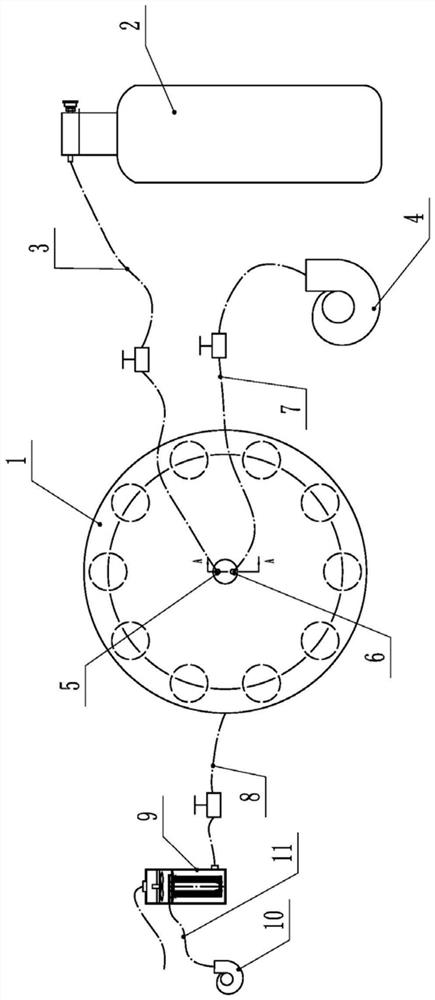
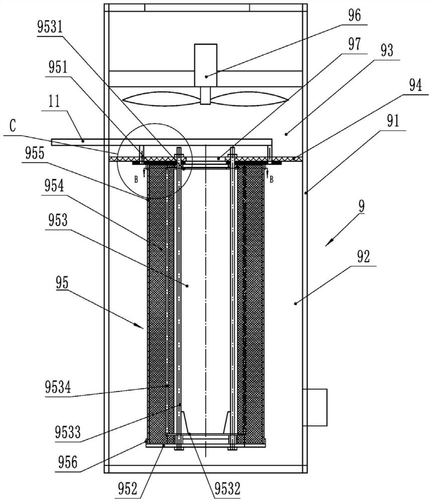
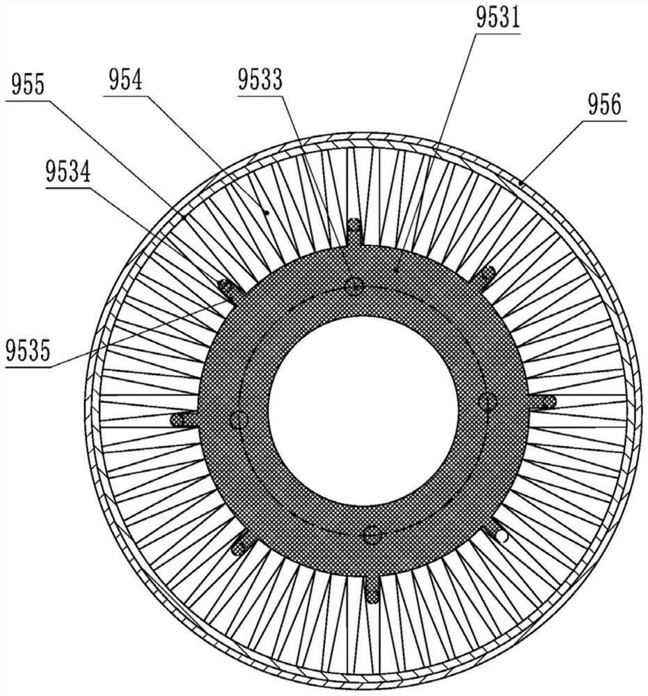
[0026] like Figure 1 to Figure 5 As shown, a MOCVD system reaction chamber cleaning device includes a reaction chamber 1 with a heating device. The heating device is an electric heating device that comes with the reaction chamber 1. In the normal production process of MOCVD, the electric heating device also needs The reaction temperature is controlled by heating, and the reaction chamber 1 is provided with a chlorine gas inlet 5 and a cleaning gas inlet 6, and the chlorine gas inlet 5 communicates with the chlorine gas storage bottle 2 through a chlorine gas supply pipeline 3, and the The cleaning inlet 6 is communicated with the purge system through the purge pipeline 7, and the reaction chamber 1 is also provided with an air outlet, which is connected with a filter 9 through an air outlet pipeline 8, and the outlet pipeline 8, chlorine gas supply Both the pipeline 3 and the ...


PUM


Abstract

The invention discloses an MOCVD system reaction cavity cleaning device which comprises a reaction cavity with a heating device, a chlorine gas inlet and a sweeping gas inlet are formed in the reaction cavity, the chlorine gas inlet is communicated with a chlorine gas storage bottle, the sweeping gas inlet is communicated with a purging system, a gas outlet is further formed in the reaction cavity and is connected with a filter, and the filter is connected with a filter. The filter comprises a box body, a partition plate is arranged on the box body and divides the box body into an air inlet cavity and an air outlet cavity, a communicating hole is formed in the partition plate, a filter element assembly is fixed to the portion, located in the air inlet cavity, of the partition plate, an exhaust port is formed in the air outlet cavity, an air exhaust fan is fixed to the interior of the air outlet cavity, and an inner cavity of the filter element assembly is communicated with the communicating hole. The air inlet cavity is provided with an air supply port which is communicated with an air supply cooling system. The cleaning device can clean the reaction cavity on line, so that the shutdown frequency is reduced, the production efficiency is improved, and the consistency of products is ensured.

Description

technical field [0001] The invention relates to a cleaning device, which is used for cleaning the inside of a reaction chamber of an MOCVD system. Background technique [0002] MOCVD is a new type of vapor phase epitaxial growth technology developed on the basis of vapor phase epitaxial growth (VPE). MOCVD uses organic compounds of group III and group II elements and hydrides of group V and group VI elements as crystal growth source materials, and performs vapor phase epitaxy on the substrate in a thermal decomposition reaction mode to grow various main group III-V, Thin-layer single-crystal materials of II-VI subgroup compound semiconductors and their multiple solid solutions. In this system, the reaction chamber is composed of a quartz tube and a graphite base. In order to grow compound semiconductor materials with uniform components, ultra-thin layers, and heterogeneous structures, some residual substances will appear in the reaction chamber during the working process. ...

Claims


Application Information

Patent Timeline
Patent Type & Authority Applications(China)
IPC IPC(8): C30B25/02C30B25/14C30B25/10C23C16/44B01D46/00B01D46/24B01D46/52
CPCC30B25/02C30B25/14C30B25/10C23C16/4405C23C16/4412B01D46/521B01D46/2411
Inventor 胡国东孔丽英翟小林
Owner 苏州耘林芯半导体科技有限公司
Why Eureka
Try Eureka