
High-temperature desulfurization and denitrification flue gas dust removal system

A desulfurization, denitrification, and dust removal system technology, applied in the direction of gas treatment, dispersed particle filtration, combined devices, etc., can solve the problems of complex management and long process flow, and achieve the effects of simplified process flow, high dust removal efficiency, and long service life

Inactive Publication Date: 2018-11-13
SHENZHEN TRIUMPH TECH ENG +1
View PDF8 Cites 2 Cited by
  • Summary
  • Abstract
  • Description
  • Claims
  • Application Information

AI Technical Summary

Problems solved by technology

[0004] The purpose of the present invention is to provide a high-temperature desulfurization and denitrification flue gas dust removal system, which can overcome the defects of long traditional desulfurization and denitrification process flow and complicated management, and utilize the advantages of high temperature resistance and high dust removal efficiency of ceramic filter dust removal to simplify the process flow. Improve efficiency

Method used


Image

  • High-temperature desulfurization and denitrification flue gas dust removal system
  • High-temperature desulfurization and denitrification flue gas dust removal system
  • High-temperature desulfurization and denitrification flue gas dust removal system

Examples


Embodiment Construction

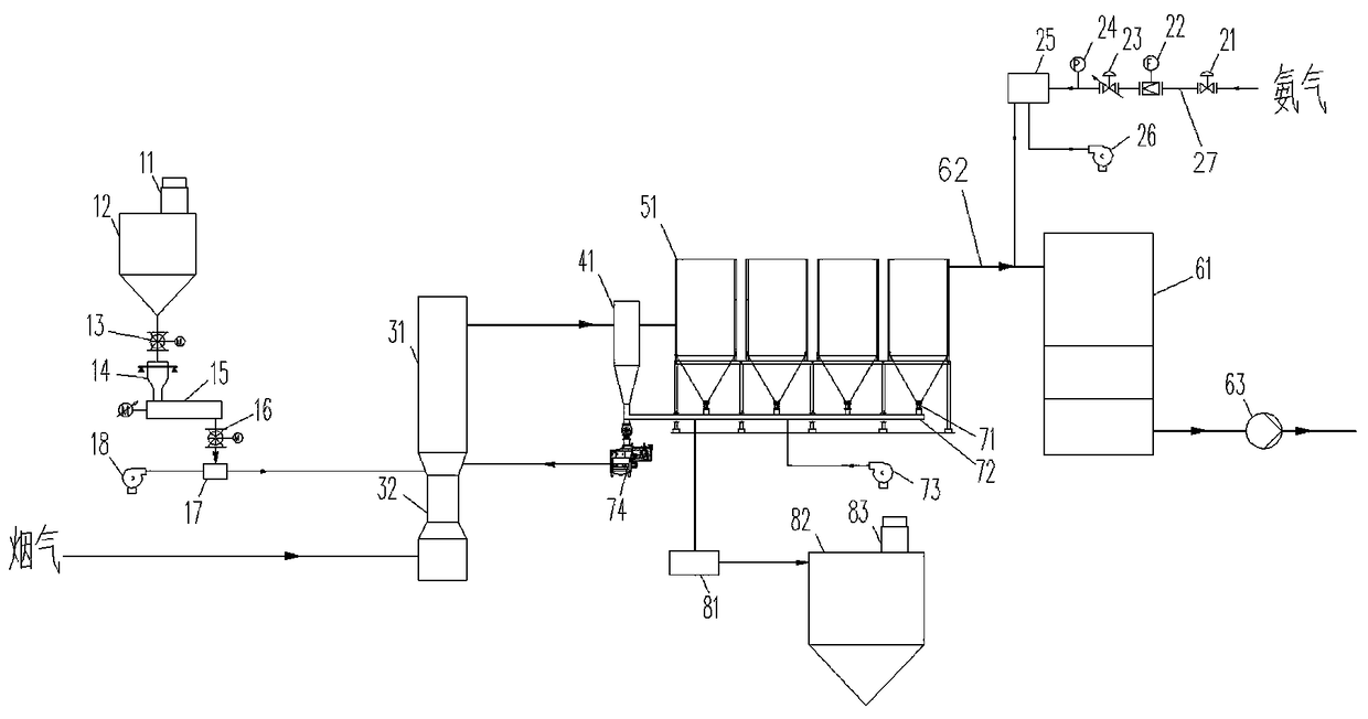
[0037] Such as figure 1 As shown, the present invention provides a high-temperature desulfurization and denitrification flue gas dust removal system, comprising:

[0038] a. Lime storage and transportation department,

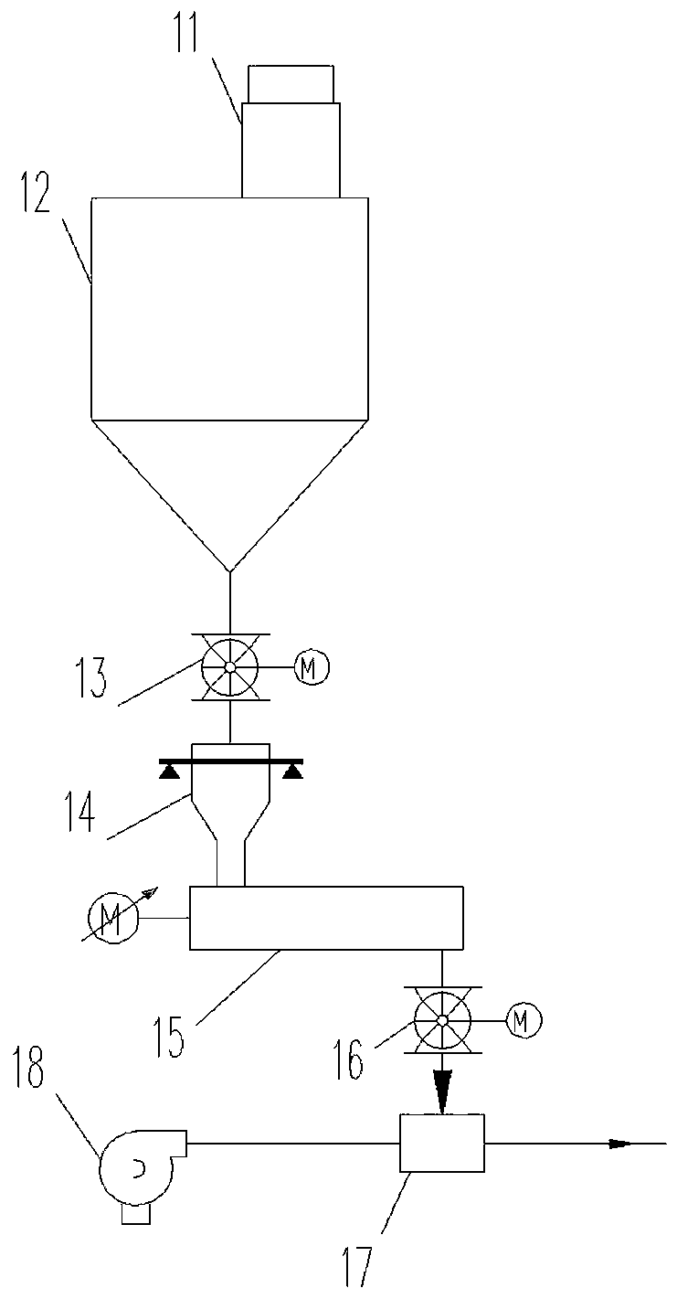
[0039] combine figure 2 As shown, the lime storage and transportation section includes a slaked lime storage bin 12, and the top of the slaked lime storage bin 12 is provided with a first dust collector 11; the bottom of the slaked lime storage bin 12 is provided with a first rotary valve 13. A weighing bin 14, a screw conveyor 15, a second rotary valve 16, and a gas-solid mixing bin 17 connected in sequence are provided; the two inlets of the gas-solid mixing bin 17 are respectively connected to the outlet of the conveying fan 18 and the second rotary valve 16;

[0040] b. Desulfurization settling part,

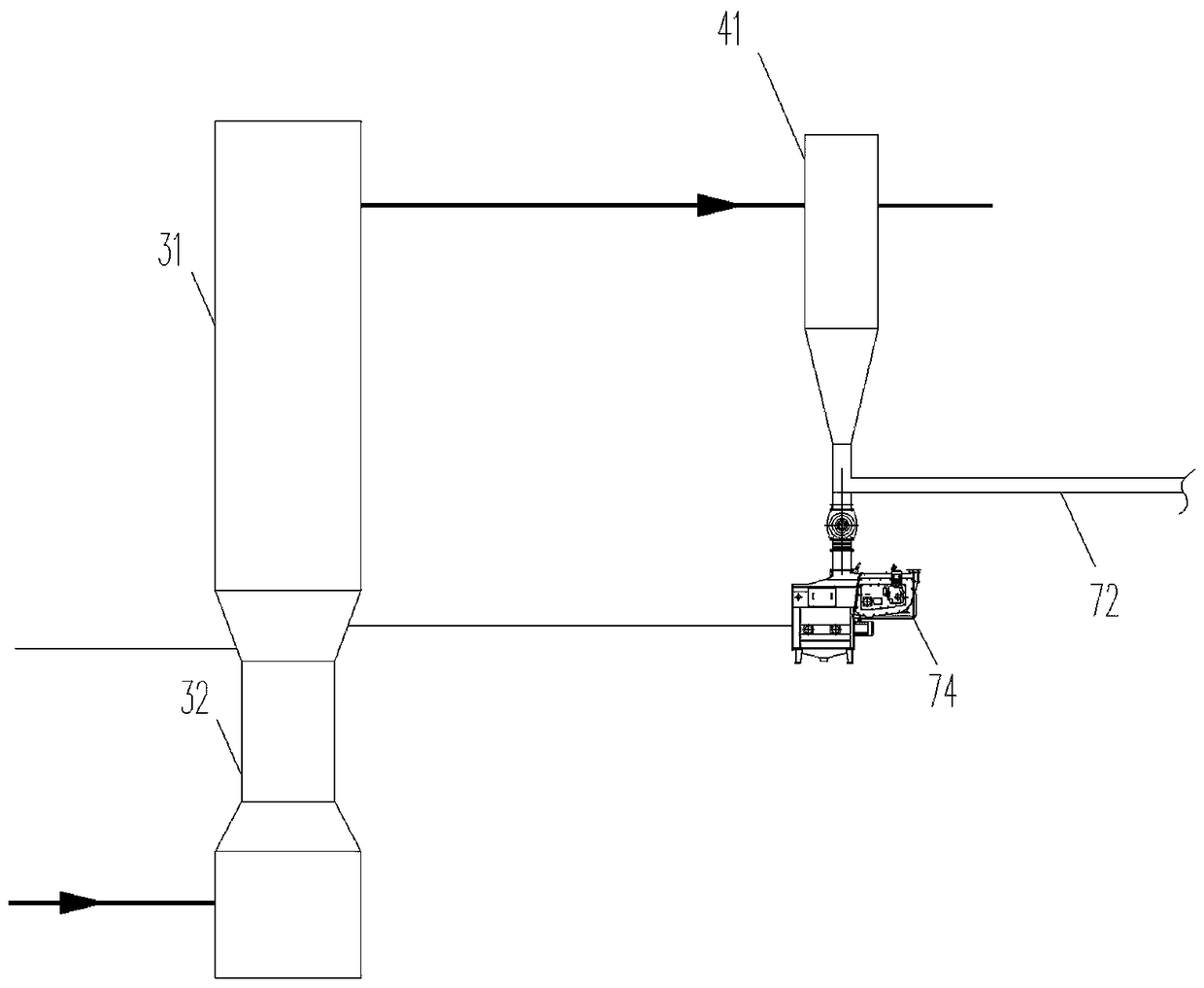
[0041] combine image 3 As shown, the desulfurization settling part includes a dry desulfurization tower 31 and a settling chamber 41. The dry desulfuri...


PUM


Abstract

The invention discloses a high-temperature desulfurization and denitrification flue gas dust removal system, which comprises a lime storage and conveying part, a desulfurization settling part, a contact agent filter part, a denitrification part, an ammonia gas supply part, a slaked lime circulating part and a byproduct collection part, wherein all the components cooperate with one another to forman organic whole; a dry desulfurization tower and a slaked lime cyclic use technology are adopted to control SO2 treatment of flue gas of a glass melter, so that under the conditions of a high cycle ratio and relatively low Ca / S, SO2 discharge is standardized, and desulfurization treatment is completed at a high-temperature section in combination with a contact agent filter dust remover; meanwhile, desulfurized byproducts enter the contact agent filter dust remover for dust removal, so that the concentration of particulate matters in the flue gas is reduced, and a rear-end SCR denitrificationreactor is protected; the SCR denitrification reactor is adopted to control nitric oxide, so that a catalyst is protected; meanwhile, no particulate matters are produced in the denitrification reaction, so that the concentration of the particulate matters discharged by the flue gas cannot be increased.

Description

technical field [0001] The invention relates to the field of flue gas treatment of flat glass melting furnaces, in particular to a high-temperature desulfurization and denitrification flue gas dust removal system. Background technique [0002] At present, the treatment of nitrogen oxides in the glass industry is generally to install the SCR denitrification reactor after the high-temperature electrostatic precipitator. At the same time, the desulfurization process is to use semi-dry or wet desulfurization technology after the waste heat boiler is cooled. The technological process is complicated, the floor area is large, and the management is difficult. [0003] Ceramic filter dust removal has been initially applied to the market. It has the characteristics of high temperature resistance, chemical corrosion resistance, and high dust removal efficiency. At present, there are finished products on the market both at home and abroad. There are two types of ceramic filter dust rem...

Claims


Application Information

Patent Timeline
Patent Type & Authority Applications(China)
IPC IPC(8): B01D53/75B01D53/81B01D53/86B01D53/56B01D53/50B01D53/48B01D50/00B01D46/00B01D45/02
CPCB01D45/02B01D46/00B01D53/48B01D53/508B01D53/75B01D53/81B01D53/8625B01D2251/2062B01D2251/404B01D2258/0283B01D50/20
Inventor 刘科李金虎谷化强汤红运李华东吴飞张立凯
Owner SHENZHEN TRIUMPH TECH ENG
Learn More