Water heater with micro-nano bubble water generating device and control method thereof
A technology of micro-nano bubbles and generating devices, which is applied in chemical instruments and methods, mixing methods, fluid heaters, etc., can solve the problems of potential safety hazards, high noise, and difficulty in ensuring the mixing effect of gas and liquid in the gas mixing tank. Improve user experience and ensure cleaning effect
- Summary
- Abstract
- Description
- Claims
- Application Information
AI Technical Summary
Problems solved by technology
Method used
Image

Examples
Embodiment 1
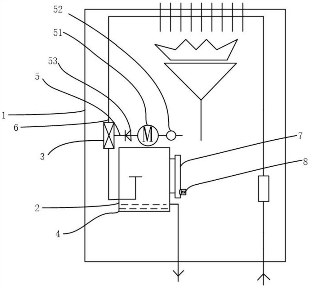
[0040] see figure 1 Shown is a water heater with a micro-nano-bubble water generating device, including a water heater body 1 and a micro-nano-bubble water generating device 2, the micro-nano-bubble water generating device 2 is arranged in the water heater body 1, and the micro-nano-bubble water The water generating device 2 includes a jet device 3, an air mixing tank 4, an air inlet pipe 5 and a water inlet pipe 6. The water inlet pipe 6 communicates with the water flow pipeline inside the water heater body 1. The water outlet end of the water inlet pipe 6 and the The air outlet end of the air inlet pipe 5 is communicated with the jet device 3, the water outlet end of the jet device 3 is communicated with the water inlet end of the mixing tank 4, and an air pump 51 and an air pump 51 are also arranged on the air inlet pipe 5. Gas flow meter 52.
[0041] The present invention proposes a water heater with micro-nano bubble water generating device 2, the user can choose to ente...
Embodiment 2
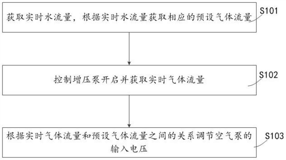
[0054] see figure 2 Show a kind of control method that has micronano-bubble water generating device water heater, be applied in a kind of water heater with micro-nano-bubble water generating device described in embodiment one, comprise the steps:
[0055] Step S101, obtaining the real-time water flow, and obtaining the corresponding preset gas flow according to the real-time water flow;
[0056] Step S102, controlling the booster pump to start and obtaining real-time gas flow;
[0057] Step S103, adjusting the input voltage of the air pump according to the relationship between the real-time gas flow and the preset gas flow.
[0058] The present invention proposes a control method for a water heater with a micro-nano bubble water generating device. Every time a user uses the water heater, the water flow rate will be different. By obtaining the real-time water flow rate to obtain the preset gas flow rate corresponding to the real-time water flow rate, Control the opening of t...
PUM
 Abstract
Description
Claims
Application Information