Multi-machine-head single-return-stroke segmented compression type water chilling unit

A technology of segmented compression and chiller, applied in compressors, compressors, irreversible cycle compressors, etc., can solve the problems of low cooling efficiency and unmatched chilled water flow and cooling capacity.

Pending Publication Date: 2021-11-02
JIANGSU QUYU ENERGY CO LTD
View PDF4 Cites 1 Cited by
  • Summary
  • Abstract
  • Description
  • Claims
  • Application Information

AI Technical Summary

Problems solved by technology

Therefore, during most of the running time, the chilled water flow of the chiller is in a situation that does not match the cooling capacity, resulting in a low efficiency of the chiller.

Method used


Image

  • Multi-machine-head single-return-stroke segmented compression type water chilling unit

Examples


Embodiment 1

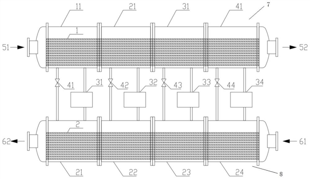
[0018] Such as figure 1 As shown, this embodiment provides a multi-head single-return segmental compression chiller, including a combined condenser 7 and a combined evaporator 8, and the combined condenser 7 is sequentially connected and combined by four segmented condensers. The two ends of the combined condenser 7 are respectively the condenser inlet 51 and the condenser outlet 52, and the four section condensers are respectively the first section condenser 11 and the second section condenser from the condenser inlet 51 to the condenser outlet 52. Sectional condenser 21, the third section condenser 31 and the fourth section condenser 41, the combined condenser 7 is provided with a condenser tube bundle 1 for common use by four section condensers, the combined evaporator 8 is composed of four segmented evaporators connected sequentially. The two ends of the combined evaporator 8 are the evaporator inlet 61 and the evaporator outlet 62 respectively. The four segmented evaporat...

Embodiment 2

[0023] In this embodiment, the water chiller provided in Example 1 is used as an example. First, according to the actual chilled water flow demand, the lengths of the condenser tube bundle 1 and the evaporator tube bundle 2 in the chiller in Example 1 are determined, that is, the cooling function The number of sections, four refrigeration function sections are selected in this embodiment.

[0024] During the operation of the chiller, according to the demand for terminal cooling capacity, the following conditions are met:

[0025] Case 1: When the cooling load is not greater than 25% of the rated cooling capacity of the chiller, choose to run only the first cooling function segment (or one of the other three cooling function segments), and the cooling water enters the condenser from the inlet 51 of the condenser The evaporator tube bundle 1 flows out from the condenser outlet 52 , and then the chilled water enters the evaporator tube bundle 2 from the evaporator inlet 61 and fl...


PUM


Abstract

The invention discloses a multi-machine-head single-return-stroke segmented compression type water chilling unit. The multi-machine-head single-return-stroke segmented compression type water chilling unit comprises a combined condenser and a combined evaporator; the combined condenser is formed by sequentially connecting and combining a plurality of segmented condensers, and condenser pipe bundles are arranged in the combined condenser and used for all the segmented condensers; the combined evaporator is formed by sequentially connecting and combining a plurality of segmented evaporators, evaporator pipe bundles are arranged in the combined evaporator and used for being used by all the segmented evaporators, and the segmented condensers correspond to the segmented evaporators in a one-to-one mode; and compressors are connected between the segmented condensers and the segmented evaporators which correspond to each other, and the compressor, the segmented condenser and the segmented evaporator form a refrigeration function section. The refrigerating capacity and the chilled water flow can be independently controlled according to actual requirements, the problem that the refrigerating capacity and the chilled water flow of an existing water chilling unit are difficult to match is solved, and therefore the good using effect of the water chilling unit is guaranteed.

Description

technical field [0001] The invention relates to the technical field of chillers, in particular to a multi-head, single-return segmental compression chiller. Background technique [0002] The current chillers use the cooling capacity as the primary parameter, and then determine the rated chilled water flow rate based on the rated supply and return water temperature. There is a relatively fixed relationship between the cooling capacity and the chilled water flow rate, and the chilled water flow rate is not based on It is determined by the flow rate required at the end of the project. During the operation of the chiller, the cooling capacity and the chilled water flow are often inconsistent. Specifically, under a certain load condition, the cooling capacity of a single chiller can meet the cooling capacity demand of the terminal, but the flow provided by the chiller cannot Satisfy the flow demand at the end. Because chilled water is the carrier of cold energy, insufficient ch...

Claims


Application Information

Patent Timeline
Patent Type & Authority Applications(China)
IPC IPC(8): F25B1/00F25B39/04F25B39/02F25B41/30F25B31/00
CPCF25B1/00F25B39/04F25B39/02F25B41/30F25B31/00F25B2339/04F25B2339/02F25B2400/06
Inventor 蒋家祺薛中柱
Owner JIANGSU QUYU ENERGY CO LTD
Why Eureka
Try Eureka