
Power distribution room switch cabinet temperature and humidity control system

A humidity control system and power distribution room technology, applied in control/regulation systems, non-electric variable control, substation/switch layout details, etc. Solve the effect of slow heat dissipation and speed up heat dissipation

Inactive Publication Date: 2021-11-02
霍孟蛟
View PDF0 Cites 0 Cited by
  • Summary
  • Abstract
  • Description
  • Claims
  • Application Information

AI Technical Summary

Problems solved by technology

[0005] Aiming at the deficiencies of the prior art, the present invention provides a temperature and humidity control system for the switchgear in the power distribution room, which solves the problem that the internal temperature of the traditional power distribution cabinet will rise under the action of internal and external factors, and the high temperature cannot be discharged in time, which will cause Problems of high temperature overload and high humidity short circuit

Method used


Image

  • Power distribution room switch cabinet temperature and humidity control system
  • Power distribution room switch cabinet temperature and humidity control system
  • Power distribution room switch cabinet temperature and humidity control system

Examples


Embodiment Construction

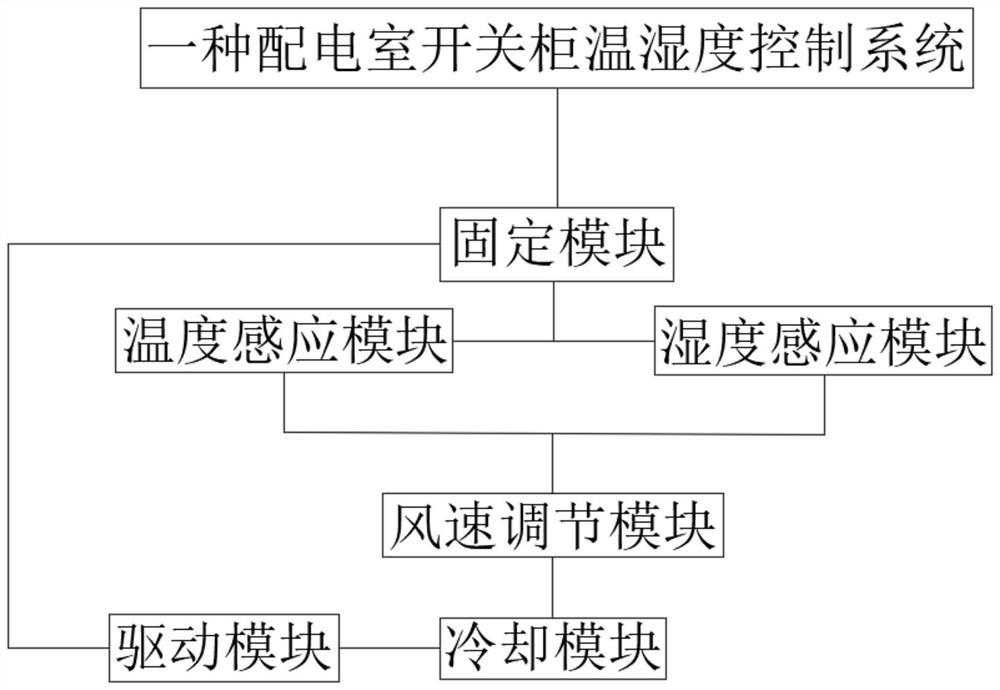
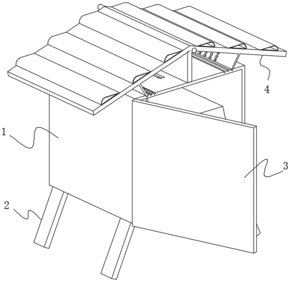
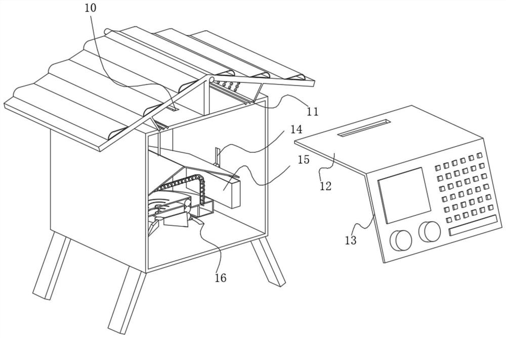
[0029] use Figure 1-Figure 6 A temperature and humidity control system for a switch cabinet in a power distribution room according to an embodiment of the present invention will be described as follows.

[0030] Such as Figure 1-Figure 6 As shown, a switch cabinet temperature and humidity control system in a power distribution room of the present invention includes a temperature sensing module; it also includes a humidity sensing module, a wind speed adjustment module, a driving module, a cooling module and a fixing module, wherein:

[0031] Humidity sensing module: monitor the air humidity inside the switch cabinet in real time to avoid circuit short circuit due to high humidity inside the equipment.

[0032] Temperature sensing module: monitor the temperature inside the switchgear in real time. Together with the humidity sensing module, when the internal temperature of the device exceeds the threshold, an alarm will be sent from the outside of the device, and the internal...


PUM


Abstract

The invention belongs to the field of power distribution, and particularly relates to a power distribution room switch cabinet temperature and humidity control system which comprises a temperature sensing module, the temperature sensing module monitors the temperature in a switch cabinet in real time, and when the temperature in equipment exceeds a threshold value in cooperation with a humidity sensing module, the exterior of the equipment emits an alarm, and meanwhile the interior is physically cooled. According to the power distribution room switch cabinet temperature and humidity control system, by arranging a protection mechanism, when the temperature in equipment is low, due to the fact that gas flows through the upper plate face and the lower plate face of an inclined plate, under the effect of a spoiler, according to the Bernoulli principle, the inclined plate is unfolded, the interior of the equipment is communicated with the outside, and outside cold air flows through a cooling mechanism and an adjusting mechanism from an air inlet groove; the air is finally discharged to the outside of the equipment, and at the same time the heat inside the equipment is taken out so as to achieve the purpose of heat dissipation and cooling, the passive cooling method is adopted, the air flow of the external environment is utilized to assist in cooling, and the problems that a traditional power distribution cabinet completely consumes external energy and is large in resource consumption during cooling are solved.

Description

technical field [0001] The invention belongs to the field of power distribution, in particular to a temperature and humidity control system for a switch cabinet in a power distribution room. Background technique [0002] The indoor power distribution place with low-voltage loads is called a power distribution room, which mainly distributes power for low-voltage users. It is equipped with medium-voltage incoming lines (may have a small number of outgoing lines), distribution transformers, and low-voltage power distribution devices. [0003] The switchgear in the traditional power distribution room is directly installed outside the power distribution room. After long-term high-temperature exposure and high-load work, the internal electrical appliances of the equipment will heat up, and the external environment will transmit heat to the interior of the equipment. Under the dual effects, the power distribution The heat dissipation speed of the cabinet will be reduced, and the ri...

Claims


Application Information

Patent Timeline
IPC IPC(8): H02B1/56H02B1/28H02B1/30H02B1/32H02B1/24G05D27/02
CPCH02B1/565H02B1/28H02B1/306H02B1/303H02B1/32H02B1/24G05D27/02
Inventor 霍孟蛟
Owner 霍孟蛟
Learn More