Front-end rear release mechanism of interventional stent conveyor, conveyor and using method

A conveyor and post-release technology, which is applied in the field of medical devices, can solve the problems of interventional stents that cannot be released, and achieve the effects of rapid release, reduced diameter, and rapid unlocking

Pending Publication Date: 2021-11-05
北京有卓正联医疗科技有限公司
View PDF0 Cites 6 Cited by
  • Summary
  • Abstract
  • Description
  • Claims
  • Application Information

AI Technical Summary

Problems solved by technology

And the rear-end component realizes the positioning lock and axial movement of the release sleeve and the screw rod through the guide locking mechanism provided on the release sleeve and the screw rod, and then realizes the positioning lock and axial movement of the moving claw on the first limiter, which can Avoid the problem of early release of the interventional bracket caused by the early unlocking of the moving claw, and at the same time avoid the problem of the interventional bracket not being released due to the failure of the moving claw to be unlocked

Method used


Image

  • Front-end rear release mechanism of interventional stent conveyor, conveyor and using method
  • Front-end rear release mechanism of interventional stent conveyor, conveyor and using method
  • Front-end rear release mechanism of interventional stent conveyor, conveyor and using method

Examples


Embodiment 1

[0088] A front-end post-release mechanism of an interventional stent delivery device, such as Figure 1-2 As shown, it includes a front end assembly 200, including a first stopper 210, a moving claw 220 sleeved on the first stopper 210, and a second stopper 230, and the first stopper 210 is provided with a The claw body 221 of the moving claw 220 matches the claw groove (2121, 2141), and the proximal end of the intervention bracket is fixed to the first stopper 210 through the cooperation of the moving claw 220 and the claw groove (2031, 2041). , the proximal end of the first stopper 210 is fixed to the guide head 100, and the distal end passes through the second stopper 230 to limit the axial sliding of the moving claw 220 to the length of the first stopper 210 Within the range, when the moving claw 220 moves at the same time, the proximal end of the interventional support can be released.

[0089] Such as image 3 As shown, from the proximal end to the distal end, the firs...

Embodiment 2

[0105] A handle that enables quick and slow release of interventional stents, such as Figure 13 As shown, it includes a handle housing 410 and a screw sleeve 420 fixed in the handle housing 410, one end of the handle housing 410 ( Figure 13 The proximal end) has an axial extension of the screw sleeve 420, and a cam ring speed switching mechanism 430 is arranged on the axial extension. in Figure 13 (a) is a structural schematic diagram of the handle of the present invention; Figure 13 (b) is a schematic cross-sectional structure diagram of the handle of the present invention in a rotating slow moving state; Figure 13 (c) is a schematic cross-sectional structure diagram of the handle of the present invention in a sliding fast moving state;

[0106] The cam ring speed switching mechanism 430 includes a cam ring 431 and a telescopic tooth plate 432 . The cam ring 431 is sleeved on the screw sleeve 420 with a clearance fit therebetween. Along the radial direction of the c...

Embodiment 3

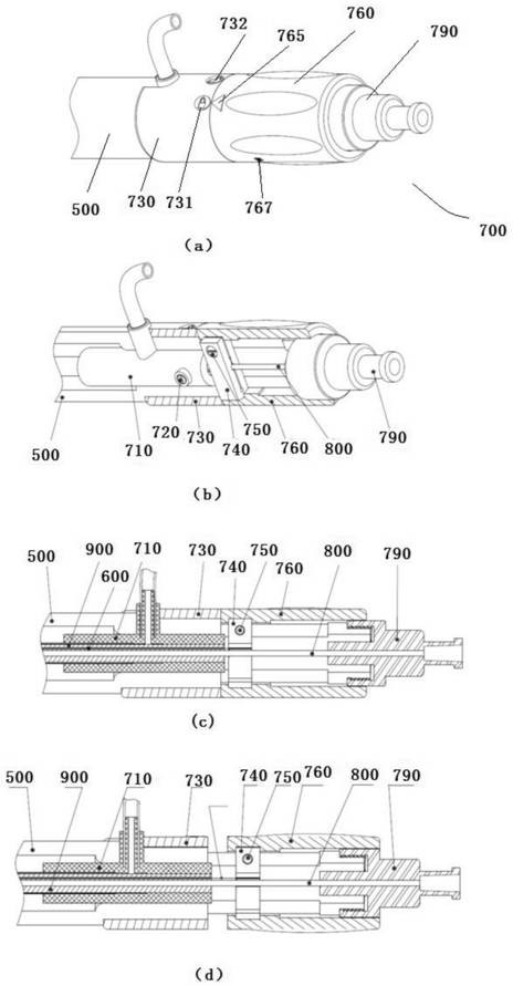
[0132] An interventional stent transporter, comprising the front-end rear release mechanism in Embodiment 1, such as Figure 21 shown, also includes:

[0133] The guide head 100, the distal end is fixed on the threaded shaft 211 of the first stopper 210 of the release mechanism after the front end;

[0134] Screw 500, the distal end is provided with the said holding sleeve shaft 540, release sleeve shaft 550 and Luer taper threaded shaft 560 in sequence;

[0135] The sheath tube 300, the proximal end is slidingly sleeved on the guide head 100, and the distal end is slidingly connected to the screw rod 500 through the sheath tube joint 441;

[0136] The core tube 800, one end is fixed to the guide head 100, and the other end is fixed to the Luer taper connector 790;

[0137] The middle tube 900, the proximal end at least protrudes from the proximal end of the screw 500, and the distal end is fixed to the screw 500 through the middle tube joint; the axis is provided with a cor...


PUM


Abstract

The invention provides a front-end rear release mechanism of an interventional stent conveyor, a conveyor and a using method. The front-end rear release function of an interventional stent is achieved by arranging a moving claw capable of moving on a first limiting piece in the axial direction on a front-end assembly and connecting the moving claw with a metal block of a rear-end assembly of the conveyor through a drawing wire. The rear end assembly realizes positioning locking and axial movement of a release sleeve and a screw rod through a guide locking mechanism arranged on the release sleeve and the screw rod, so that positioning locking and axial movement of the moving claw on the first limiting piece are realized, and the problem that the interventional stent is released in advance due to the fact that the moving claw is unlocked in advance can be solved; and meanwhile, the problem that the interventional stent cannot be released due to the fact that the moving claw cannot be unlocked can be solved. The guide locking mechanism is designed to be a guide column and an L-shaped guide groove formed in the outer surface of the screw rod, it is guaranteed that the front-end rear release mechanism is safe in self-locking and rapid in unlocking, and the safety, reliability and positioning accuracy of the conveyor are further improved.

Description

technical field [0001] The invention relates to the technical field of medical devices, in particular to a front-end rear release mechanism of an interventional stent transporter, a transporter and a use method. Background technique [0002] Aortic dissection is an acute aortic disease with a dangerous condition, rapid progress and high mortality, and its incidence accounts for about 5% to 20% of the general population. For lesions confined to the descending aorta, interventional stent-graft surgery is currently the main treatment option in clinical practice, that is, the stent-graft is pressed and held in the conveyor, and delivered to the lesion through the femoral artery incision along the guide wire. After withdrawing the outer sheath of the delivery device, the stent self-expands and opens, attaches to the vessel wall, and isolates the blood flow in the aortic dissection or tumor cavity to achieve the purpose of treatment. The whole operation process is carried out und...

Claims


Application Information

Patent Timeline
Patent Type & Authority Applications(China)
IPC IPC(8): A61F2/966A61F2/97
CPCA61F2/966A61F2/97
Inventor 于学保许尚栋赵国行伍源付天翔刘冰崔跃
Owner 北京有卓正联医疗科技有限公司
Why Eureka
Try Eureka