Membrane oxygenator

A membrane oxygenator and oxygenation technology, which is applied in the field of medical devices, can solve the problem of low blood oxygenation efficiency, achieve high oxygenation efficiency and realize the effect of uniform distribution

Pending Publication Date: 2021-11-05
CHINABRIDGE (SHENZHEN) MEDICAL TECH CO LTD
View PDF0 Cites 4 Cited by
  • Summary
  • Abstract
  • Description
  • Claims
  • Application Information

AI Technical Summary

Problems solved by technology

[0004] The purpose of the embodiments of the present invention is to provide a membran

Method used


Image

  • Membrane oxygenator
  • Membrane oxygenator
  • Membrane oxygenator

Examples


Embodiment 1

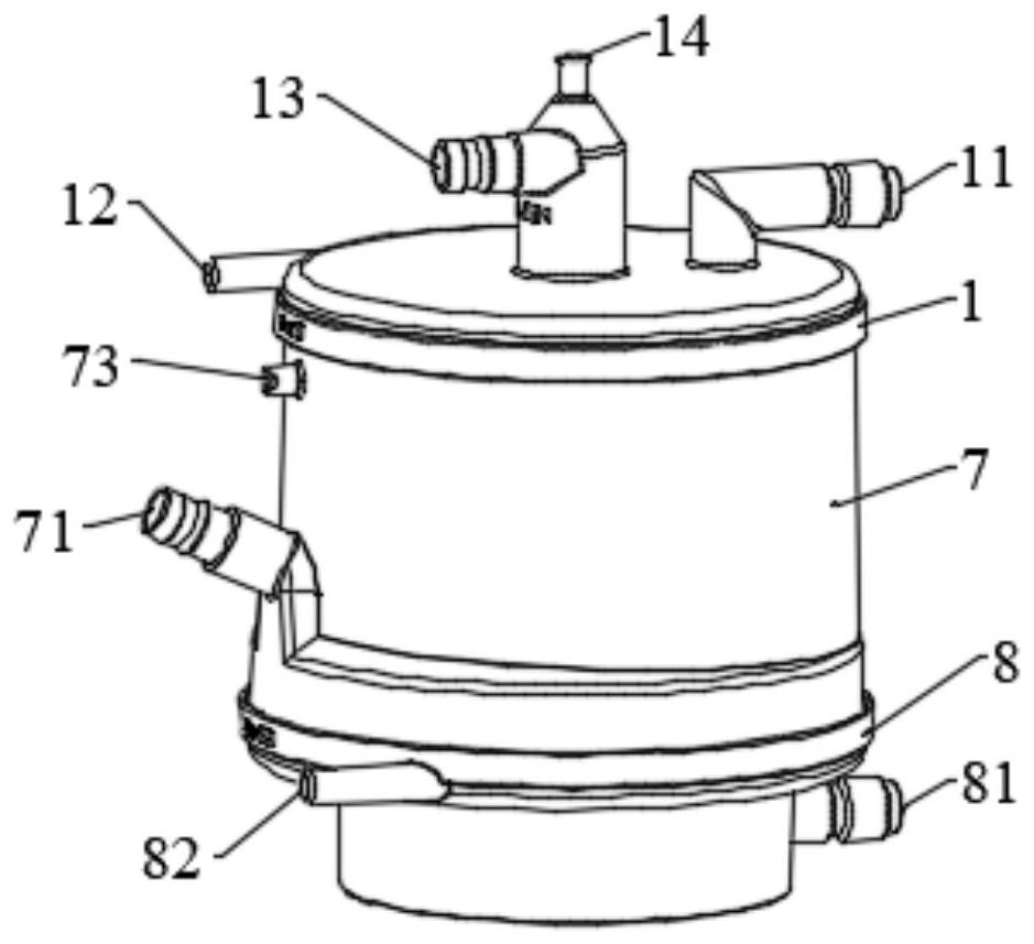
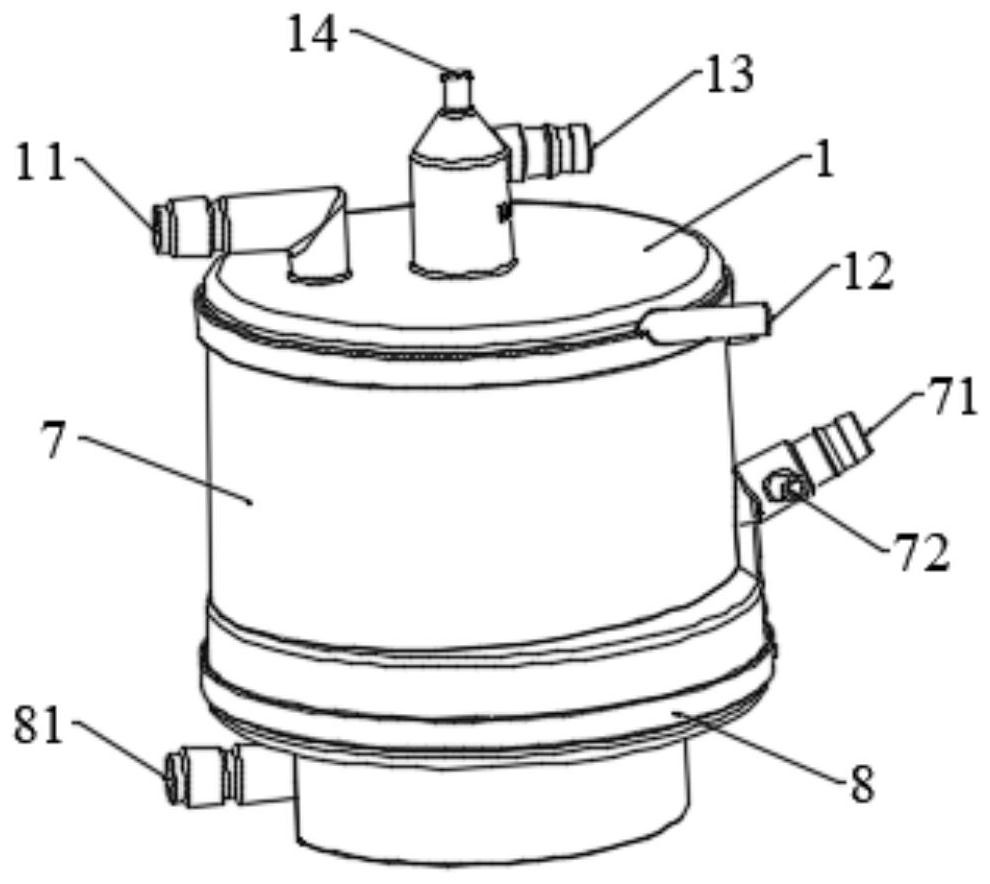
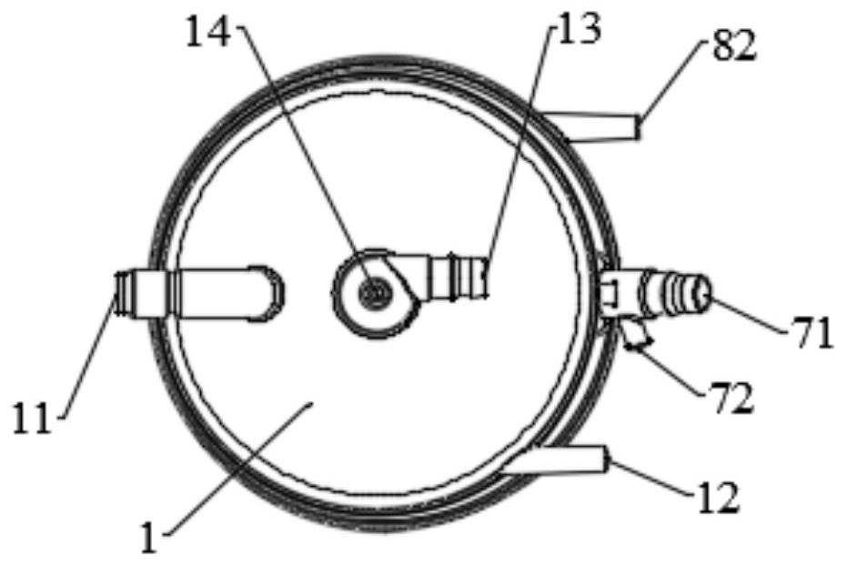
[0052] like Figure 1-4, 6-7, in a specific embodiment 1 of the present invention, a membrane oxygenator is provided, including: a housing and an oxygenation structure 6 arranged in the housing, a heat exchange structure 4 and a first A diversion structure 3, the first diversion structure 3 is vertically arranged in the middle of the housing, and the oxygenation structure 6 is sequentially sleeved on the heat exchange structure 4 and the first diversion structure 3; the housing is provided with The blood inlet channel 13 , the bleeding channel 71 , the air inlet channel 12 and the air outlet channel 82 . Wherein, the blood flows to the oxygenation structure 6 through the blood inlet channel 13 on the housing, the first flow guide structure 3 and the heat exchange structure 4 in order to carry out blood oxygenation, and the oxygenated blood through the oxygenation structure 6 The blood flows out through the bleeding channel 71 of the housing.

[0053] like Figure 4 , 8 As ...

Embodiment 2

[0078] like Figure 14-16 As shown, in another specific embodiment 2 of the present invention, a membrane oxygenator is also provided, including a housing, and an oxygenation structure 6, the first Two flow guide structures 5, a heat exchange structure 4, and a first flow guide structure 3; wherein, the first flow guide structure 3 of this embodiment 2 includes an upper flow guide structure 31 at the upper part and a lower flow guide structure 32 at the lower part, The upper flow guide structure 31 and the lower flow guide structure 32 are connected by several axially arranged connecting pieces 34, and the connecting pieces 34 are axially arranged at the edge positions of the upper flow guide structure 31 and the lower flow guide structure 32, connecting Part 34 is a strip structure. The side of the lower flow guide structure 32 is a curved concave structure, and a second gap is formed between two adjacent connecting pieces 34, and the second gap and the space between the upp...


PUM


Abstract

The embodiment of the invention provides a membrane oxygenator. The membrane oxygenator comprises a shell, an oxygenation structure, a heat exchange structure and a first flow guide structure, wherein the oxygenation structure, the heat exchange structure and the first flow guide structure are arranged in the shell; a blood inlet channel, a blood outlet channel, an air inlet channel and an air outlet channel are formed in the shell; a through hole communicated with the blood inlet channel is formed in the first flow guide structure, and a blood outlet groove communicated with the through hole is formed in the side face of the first flow guide structure; the heat exchange structure and the oxygenation structure are sequentially arranged on the periphery of the first flow guide structure from inside to outside, and the oxygenation structure is communicated with the air inlet channel and the air outlet channel in the shell; and blood sequentially passes through the blood inlet channel, the first flow guide structure and the heat exchange structure on the shell, flows to the oxygenation structure to be oxygenated and flows out of the blood outlet channel. According to the membrane oxygenator, the first flow guide structure is arranged in the middle of the interior of the shell, the effect that the blood is evenly distributed in the oxygenator is effectively achieved, and the oxygenation efficiency of the oxygenator is high.

Description

technical field [0001] The embodiments of the present application belong to the technical field of medical devices, and more specifically, relate to a membrane oxygenator. Background technique [0002] In the prior art, the membrane oxygenator is mainly used in extracorporeal circulation during cardiac surgery or treatment, and is used to temporarily replace the function of the lungs for blood oxygenation and carbon dioxide removal. The main principle of the membrane oxygenator is to turn the venous blood drawn out of the body into arterial blood after oxygenation and removal of carbon dioxide through the membrane oxygenator, and then return it to the patient to maintain the supply of oxygenated blood to human organs and tissues , and at the same time provide a favorable environment for doctors to perform operations. [0003] The current membrane oxygenator, when the blood enters the oxygenator through the blood channel, the efficiency of blood oxygenation is usually not hi...

Claims


Application Information

Patent Timeline
IPC IPC(8): A61M1/36
CPCA61M1/3621A61M1/367
Inventor 李轶江刘洋
Owner CHINABRIDGE (SHENZHEN) MEDICAL TECH CO LTD
Why Eureka
Try Eureka