Axial vibration type oil-water separator

A technology of oil-water separator and axial vibration, which is applied in the direction of filtration separation, separation method, immiscible liquid separation, etc., and can solve problems such as low processing efficiency, long processing time, and human health hazards

Pending Publication Date: 2021-11-05
广州江水青智能科技有限公司
View PDF0 Cites 2 Cited by
  • Summary
  • Abstract
  • Description
  • Claims
  • Application Information

AI Technical Summary

Problems solved by technology

[0002] Environmental protection has become the focus of today's society, and the treatment of sewage discharge has always been unsatisfactory, especially the treatment of oily wastewater has always been a concern of the environmental protection industry. A large amount of industrial wastewater and domestic sewage containing particulate matter such as oily waste residues are discharged to sewage treatment If the oily wastewater is discharged into the water environment, it will not only pollute the water body, affect the normal activities of related organisms, but also cause harm to human health.
[0003] The existing traditional sewage containing particulate matter such as oily waste residue generally adopts physical purification to filter the water quality, and the impurities in the sewage are filtered out through the filter screen. You need to remove the filter regularly for cleaning
This leads to the disadvantages of low processing efficiency, long processing time, small processing volume, slow processing speed, and unfavorable centralized processing. At the same time, there are disadvantages of high labor intensity and poor working environment.

Method used


Image

  • Axial vibration type oil-water separator
  • Axial vibration type oil-water separator
  • Axial vibration type oil-water separator

Examples


Embodiment approach

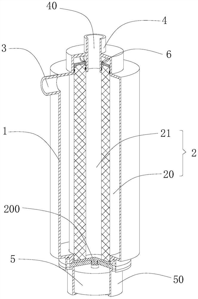
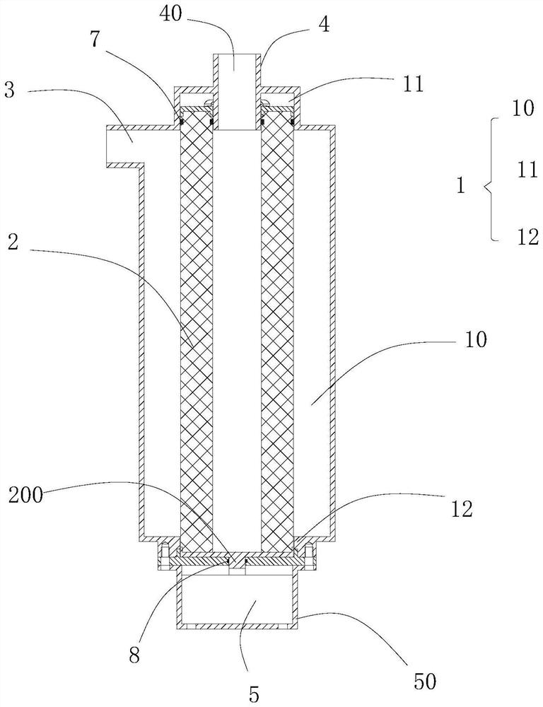
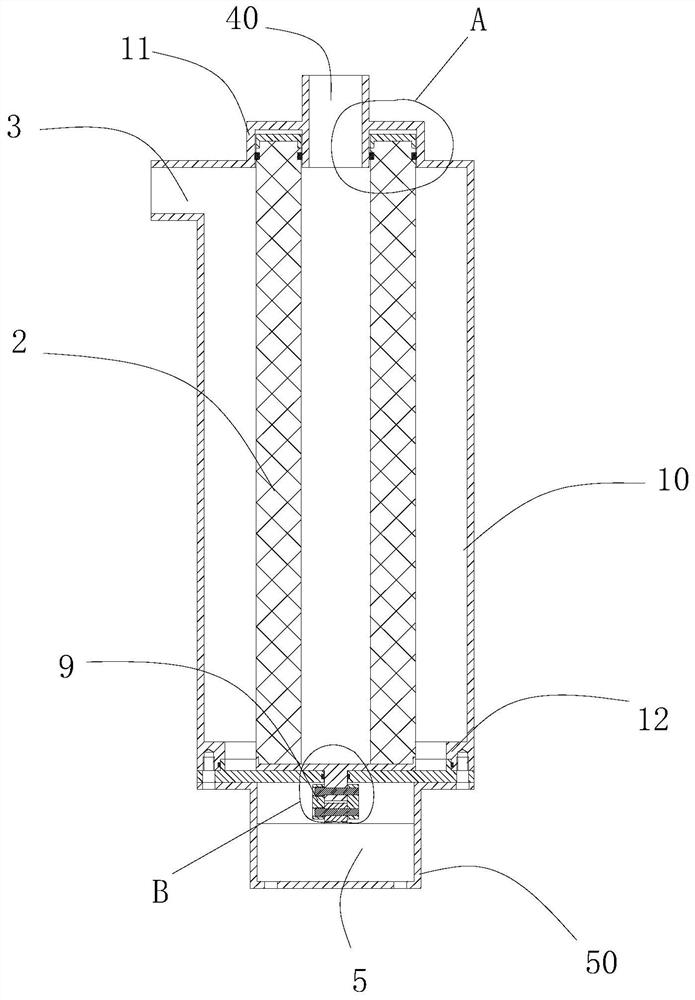
[0039] See Figure 1-10 , the present invention shows an axial vibrating oil-water separator, including a housing 1, a filter core 2 and a vibrating device 5, the housing 1 is a hollow structure, and the filter core 2 is arranged in the shell Inside the body 1, and the filter core body 2 is connected to the vibration device 5 to drive the filter core body 2 to vibrate axially; the vibration device 5 is preferably a vibration motor, and the vibration motor drives the filter core body 2 to perform axial vibration. vibration.

[0040] The housing 1 is provided with an inlet 3, so that the liquid to be filtered enters the housing 1 from the inlet 3, and the filter core 2 is formed with an inner cavity 21 and a filter hole communicating with the inner cavity 21 (not shown), the filter core 2 is sealed with the housing 1 so that the liquid entering from the inlet 3 can only enter the inner cavity 21 through the filter hole. That is, after the oily water is filtered through the fil...


PUM


Abstract

The invention discloses an axial vibration type oil-water separator which comprises a shell, a filter element body and a vibration device, the shell is of a hollow structure, the filter element body is arranged in the shell, and one end of the filter element body is connected with the vibration device; an inlet is formed in the shell so that oily water needing to be filtered can enter the shell from the inlet, an inner cavity and filter holes communicating with the inner cavity are formed in the filter element body, so that after liquid needing to be filtered is filtered through the filter holes, greasy dirt and waste residue particles can be blocked outside the filter element body, water enters the inner cavity, and a discharge port communicating with the inner cavity is further formed in the shell, so that water in the inner cavity can be discharged from the discharge port. When the filter element body is cleaned, the vibration device can drive the filter element body to axially vibrate, so that oil stains and waste residue particles accumulated on the filter element body are vibrated into the shell, cleaning water entering from the discharge port enters the shell through the filter holes, the oil stains and the particles can be discharged from the inlet, and the effect of centralized and efficient treatment is achieved.

Description

technical field [0001] The invention relates to the technical field of sewage treatment equipment, in particular to an axial vibration type oil-water separator. Background technique [0002] Environmental protection has become the focus of today's society, and the treatment of sewage has always been unsatisfactory, especially the treatment of oily wastewater has always been a concern of the environmental protection industry. A large amount of industrial wastewater and domestic sewage containing particulate matter such as oily waste residues are discharged to sewage treatment If the oily wastewater is discharged into the water environment, it will not only pollute the water body, affect the normal activities of related organisms, but also cause harm to human health. [0003] The existing traditional sewage containing particulate matter such as oily waste residue generally adopts physical purification to filter the water quality, and the impurities in the sewage are filtered o...

Claims


Application Information

Patent Timeline
Patent Type & Authority Applications(China)
IPC IPC(8): B01D36/00B01D17/02B01D33/03B01D33/54B01D33/76B01D33/50B01D33/80
CPCB01D36/003B01D17/02B01D33/03B01D33/54B01D33/76B01D33/50B01D33/801
Inventor 陈浩航陈宇航
Owner 广州江水青智能科技有限公司
Why Eureka
Try Eureka