Sand mold assembly workbench suitable for dieless composite forming process

An assembly workbench and compound forming technology, applied to workbenches, manufacturing tools, etc., can solve the problems of long process time, high labor costs, and assembly scenarios that can only be applied to fixed assembly methods, so as to reduce the operation process time, Labor saving effect

Pending Publication Date: 2021-11-05
ADVANCED MFG TECH CENT CHINA ACAD OF MASCH SCI & TECH
View PDF11 Cites 6 Cited by
  • Summary
  • Abstract
  • Description
  • Claims
  • Application Information

AI Technical Summary

Problems solved by technology

[0003] 1. There is a problem of poor adaptability for mass production of sand molds using automatic, semi-automatic assembly lines or manual assembly;
[0004] 2. For the research and development of sand molds, most of the assembly work is done manually or with the help of auxiliary mechanical equipment, which is cumbersome to operate, takes a long time to process, and has high labor costs, low safety and low assembly efficiency
[0006] The existing sand mold assembly process generally uses manual or manual auxiliary mechanical equipment to move, flip, assemble, etc., and individual sand mold assembly scenes are transported and assembled by automated machinery, but there are many restrictions. For example, manual methods cannot Avoid the problems of long process time, low assembly efficiency and poor safety; the automatic mechanical method can only realize the assembly work of a single or a small number of sand molds, and secondly, it can only be applied to the assembly scene of the fixed assembly method

Method used


Image

  • Sand mold assembly workbench suitable for dieless composite forming process
  • Sand mold assembly workbench suitable for dieless composite forming process
  • Sand mold assembly workbench suitable for dieless composite forming process

Examples


Embodiment Construction

[0034]In order to make the object, technical solution and advantages of the present invention clearer, the present invention will be further described in detail below in conjunction with the accompanying drawings and embodiments. It should be understood that the specific embodiments described here are only used to explain the present invention, not to limit the present invention.

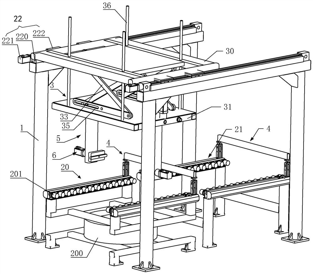
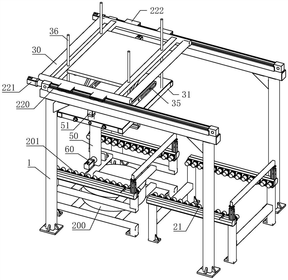
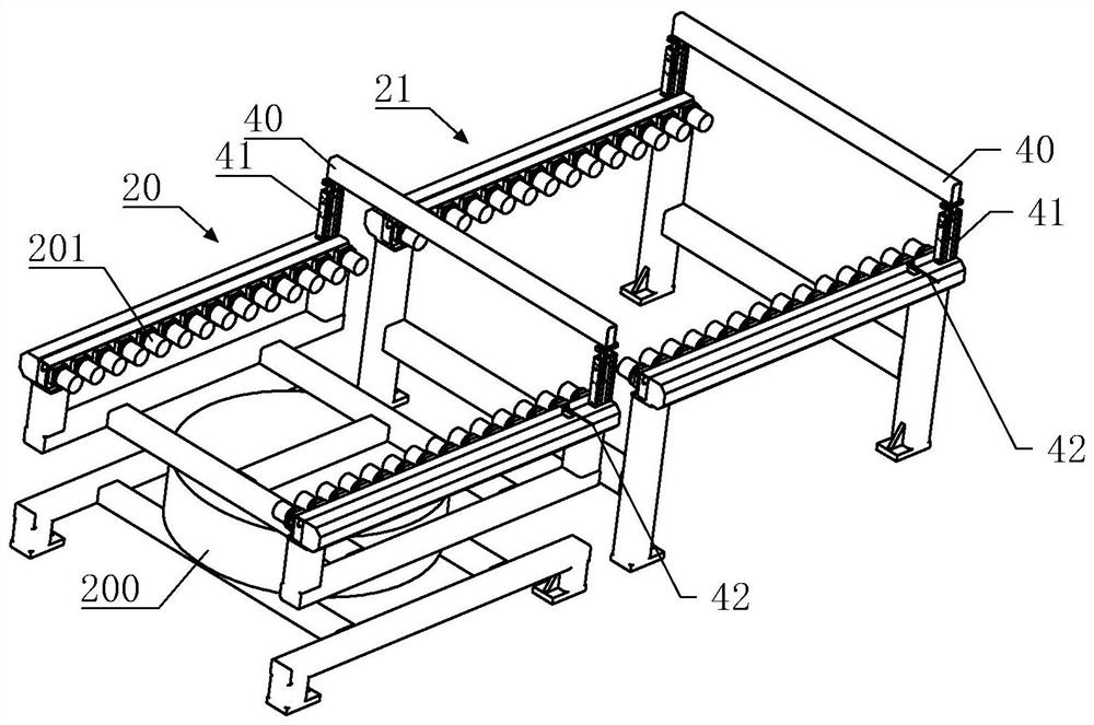
[0035] Such as Figure 1 to Figure 3 As shown together, a sand mold assembly workbench suitable for the moldless composite forming process includes a clamping mechanism 5 for clamping sand molds, an overturning mechanism 6 for flipping sand molds, a lifting mechanism 3 and a conveying mechanism, and the lifting mechanism 3 The clamping mechanism 5 and the turning mechanism 6 are arranged on it, and the lifting mechanism 3 is used to drive the clamping mechanism 5 and the lifting mechanism 3 to lift; the conveying mechanism is used to drive the lifting mechanism 3, the clamping mechanism 5 and the tu...


PUM


Abstract

The invention discloses a sand mold assembly workbench suitable for a dieless composite forming process. The sand mold assembly workbench comprises a clamping mechanism, a turnover mechanism, a lifting mechanism and a conveying mechanism, and the clamping mechanism and the turnover mechanism are arranged on the lifting mechanism; the conveying mechanism drives the lifting mechanism, the clamping mechanism and the turnover mechanism to move, and / or drives a sand mold to move; and the lifting mechanism is used for driving the clamping mechanism and the lifting mechanism to ascend and descend. After the sand mold is placed in place, the conveying mechanism drives the lifting mechanism, the clamping mechanism and the turnover mechanism to move to the position above the sand mold, the lifting mechanism drives the clamping mechanism and the turnover mechanism to descend, after the sand mold is placed in place, the clamping mechanism clamps the sand mold, the lifting mechanism ascends again, the conveying mechanism acts to drive the sand mold to move to an assembly station, and the turnover mechanism acts to drive the sand mold to turn over; and after overturning is completed, the lifting mechanism descends, the clamping mechanism loosens the sand mold, and the conveying mechanism can convey the sand mold. Therefore, the sand mold assembly workbench can realize overturning, clamping, transferring, assembling and the like of the sand mold, so that the process time is shortened, and the labor force is saved.

Description

technical field [0001] The invention relates to the technical field of assembly workbenches, in particular to a sand mold assembly workbench suitable for a moldless composite forming process. Background technique [0002] With the development of globalization, China's foundry equipment is showing an upward trend year by year, and the required casting output will inevitably increase. However, there are two problems in the sand mold assembly process in the casting production process: [0003] 1. There is a problem of poor adaptability for mass production of sand molds using automatic, semi-automatic assembly lines or manual assembly; [0004] 2. For the research and development of sand molds, most of the assembly work is done manually or with the help of auxiliary mechanical equipment. The operation is cumbersome, the process takes a long time, the labor cost is high, and the safety and assembly efficiency are low. [0005] In order to realize the automatic assembly process o...

Claims


Application Information

Patent Timeline
Patent Type & Authority Applications(China)
IPC IPC(8): B25H1/00
CPCB25H1/00
Inventor 洪海春刘森林杨文亮徐继福王志冰景文霞
Owner ADVANCED MFG TECH CENT CHINA ACAD OF MASCH SCI & TECH
Why Eureka
Try Eureka