
Emergency buffer device capable of preventing lift car from rushing to top and elevator using emergency buffer device

A buffer device, elevator technology, applied in the direction of hoisting device, transportation and packaging, elevators, etc., can solve the problems of reduced braking effect of brakes, wear or corrosion of pads and brake wheels, failure, etc., to ensure the braking effect. , to avoid the effect of the top

Inactive Publication Date: 2021-11-05
广州元坤新材料有限公司
View PDF0 Cites 7 Cited by
  • Summary
  • Abstract
  • Description
  • Claims
  • Application Information

AI Technical Summary

Problems solved by technology

[0004] The object of the present invention is to provide a method that can slow down the speed of the elevator car to a stop when the elevator car rises too fast, can buffer the elevator car when the elevator car rises to a high-level out of control, and can protect the elevator car. The emergency buffer device that can prevent the elevator car from rushing to the top and the elevator that selects the device can solve the problem that the contact point of the elevator brake in the above-mentioned background technology will be caused by excessive use time or long service life. The friction between the block and the brake wheel will cause wear or corrosion, and the braking effect of the brake will decrease or fail.

Method used


Image

  • Emergency buffer device capable of preventing lift car from rushing to top and elevator using emergency buffer device
  • Emergency buffer device capable of preventing lift car from rushing to top and elevator using emergency buffer device
  • Emergency buffer device capable of preventing lift car from rushing to top and elevator using emergency buffer device

Examples


Embodiment 1

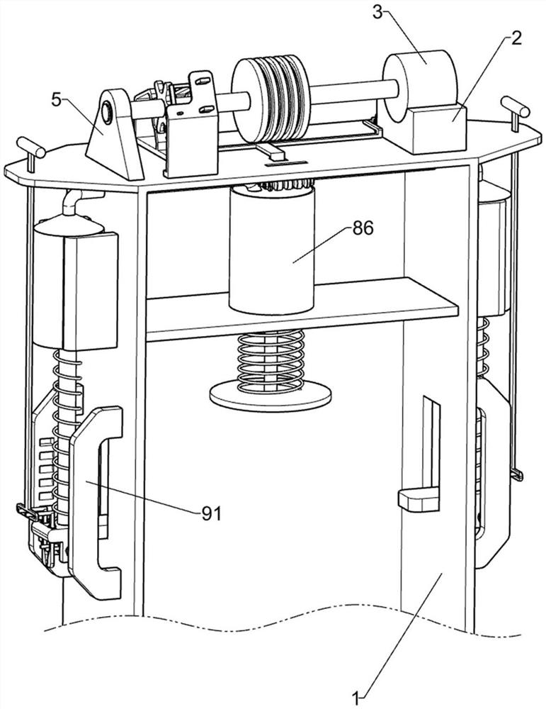
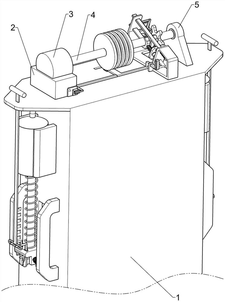
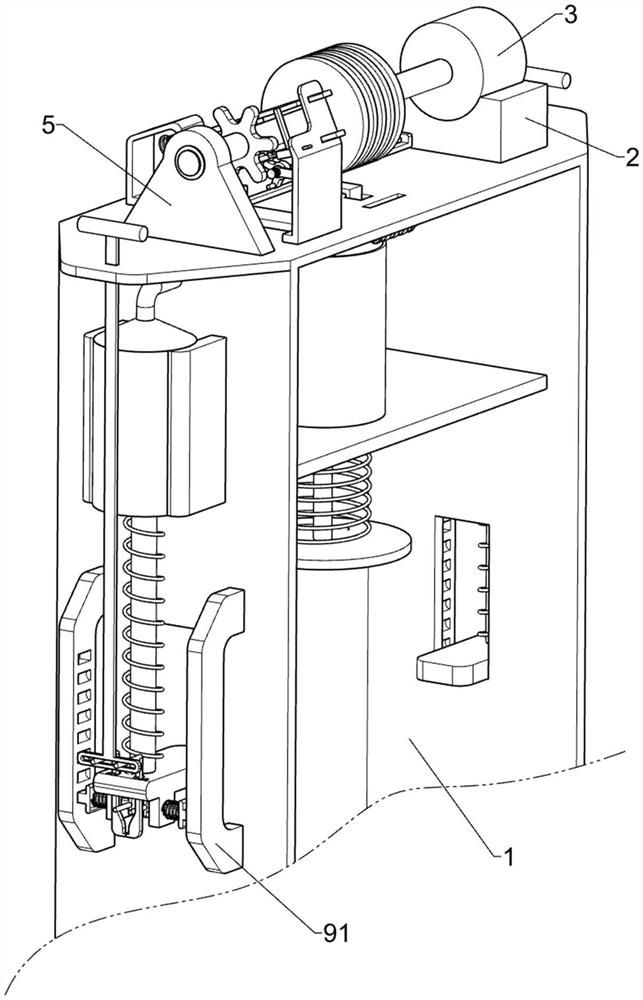
[0043] An emergency buffer device capable of preventing the car from rushing to the top and an elevator using the device, such as figure 1 , figure 2 , image 3 , Figure 4 , Figure 5 , Figure 6 , Figure 7 , Figure 8 and Figure 9 As shown, it includes an elevator derrick 1, a mounting seat 2, a servo motor 3, a power shaft 4, a triangular support 5, an overspeed trigger mechanism 6 and a traction rope limiting mechanism 7, and the right side of the top surface of the elevator derrick 1 is fixedly installed with a mounting seat. 2. The drive servo motor 3 is fixedly installed on the mounting base 2, the power shaft 4 is welded to the left end of the output shaft of the servo motor 3, the triangular support 5 is fixedly installed on the left side of the top surface of the elevator derrick 1, the triangular support 5 and the power shaft 4 Rotary connection, an overspeed trigger mechanism 6 is provided on the left side of the top surface of the elevator derrick 1, and...

Embodiment 2

[0049] On the basis of Example 1, such as Figure 10 , Figure 11 and Figure 12 As shown, a hydraulic buffer mechanism 8 is also included, and the elevator derrick 1 is symmetrically provided with a hydraulic buffer mechanism 8. The hydraulic buffer mechanism 8 is used to buffer the elevator car. The hydraulic buffer mechanism 8 includes a sliding plate 81, a piston cylinder 82 , piston push rod one 83, extruding spring one 84, guide tube 85, piston barrel two 86, piston rod two 87 and tension spring 88, symmetrical vertical sliding type is connected with sliding plate 81 on the elevator derrick 1, and sliding plate 81 Used to block the elevator car, the left and right sides of the elevator derrick 1 are fixed with a piston cylinder 82 for storing hydraulic oil, and the top surface of the sliding plate 81 is vertically connected with a piston push rod 83, which is used to push the hydraulic pressure. The oil moves upwards, the piston push rod one 83 is slidingly connected w...

Embodiment 3

[0052] On the basis of Example 2, such as Figure 13 and Figure 14 As shown, it also includes a clamping and locking mechanism 9, which is symmetrically slidably connected with a clamping and locking mechanism 9 below the sliding plate 81, and the clamping and locking mechanism 9 is used to block the sliding plate 81 and the upper device, and the clamping lock The tightening mechanism 9 includes a fixed groove seat 91, a locking lever 92, a compression spring 93, a movable protruding rod 94 and a slotted pull bar 95, and a pair of fixed groove seats 91 are fixedly connected to the elevator derrick 1 both sides, and the fixed groove seats 91 face each other. There are slots in a uniform arrangement on one side, and a locking lever 92 is connected symmetrically slidingly below the sliding plate 81. At least a part of the locking lever 92 is inserted into the slot, and the fixed groove seat 91 is used to lock the locking lever The rod 92 is blocked, and a compression spring 93 ...


PUM


Abstract

The invention discloses an emergency buffer device capable of preventing a lift car from rushing to the top and an elevator using the emergency buffer device. The emergency buffer device comprises an elevator derrick, a mounting seat, a servo motor, a power shaft and the like. The mounting seat is fixedly mounted on the right side of the top face of the elevator derrick, the servo motor is fixedly mounted on the mounting seat, and the power shaft is welded to the left end of an output shaft of the servo motor. Speed reduction calipers make contact with the power shaft, the speed reduction calipers exert resistance on the power shaft, so that the rotating speed of the power shaft and the rotating speed of devices on the power shaft are gradually decreased, meanwhile, through the effect of a first compression spring, a shifting clamping rod limits a movable limiting wheel, the rotating speed of the movable limiting wheel is decreased, the lifting speed of the lift car is decreased, then the lift car can stop in the gradual deceleration process, and the phenomenon that the lift car ascends too fast and rushes to the top when the braking effect of a brake is insufficient is prevented.

Description

technical field [0001] The invention relates to the field of elevator safety, in particular to an emergency buffer device capable of preventing a car from rushing to the roof and an elevator using the device. Background technique [0002] Along with the continuous growth of elevator utilization rate, followed by the high number of elevator accidents, the safety of elevators has become a new hidden danger for urban public safety. In moving occasions, the elevator brake is an important safety device for the elevator. The safety and reliability of the elevator brake is one of the important factors to ensure the safe operation of the elevator. Next, it forms a friction brake for power-off braking, thus ensuring the safety of the elevator. [0003] With the long-term use of the elevator, the contact point of the elevator brake will have problems due to long-term use or long-term use, resulting in poor contact or adhesion of the elevator brake contact point, and the contact effec...

Claims


Application Information

Patent Timeline
Patent Type & Authority Applications(China)
IPC IPC(8): B66B5/04B66B5/28B66B5/18B66D5/08
CPCB66B5/04B66B5/282B66B5/044B66B5/18B66D5/08
Inventor 易莫云
Owner 广州元坤新材料有限公司
Learn More