Biomass efficient clean charcoal and gas poly-generation device

A clean carbon and biomass technology, applied in the manufacture of combustible gas, petroleum industry, etc., can solve the problems of low calorific value of gas, reduced resources, difficult sealing, etc., achieve low tar and other impurities, reduce energy loss, Make full use of waste heat

Inactive Publication Date: 2021-11-05
HEFEI UNIV OF TECH
View PDF5 Cites 0 Cited by
  • Summary
  • Abstract
  • Description
  • Claims
  • Application Information

AI Technical Summary

Problems solved by technology

[0002] Energy and environmental issues have become the focus of global attention. With the rapid growth of energy consumption in China, the extensive use of fossil fuels has brought serious environmental pollution and ecological damage. Coal, oil, and natural gas are the main energy sources at this stage. Valuable organic chemical raw materials, the amount of resources is decreasing day by day, and the way that our country is generally used as fuel has caused a lot of waste. The development of clean renewable energy has become an urgent need for sustainable development. Among the renewable energy, it is the only clean energy that can be stored and transported on the earth. It has a large amount of resources, a wide distribution, and a huge development potential. Biomass gasification is one of the biomass energy utilization technologies. Among them, the fixed bed gasifier is It has the advantages of simple structure, easy manufacture, low cost, easy operation, suitable for bulk and large particle raw materials, and is suitable for rural use in China; this type of gasifier is divided into updraft gasifier and downdraft gasifier , due to structural problems, the calorific value of the gas produced by the up-suction gasifier is low, no charcoal is produced, and it is difficult to seal, and it is inconvenient to add materials. Excessive heat loss, insufficient gasification, etc.

Method used


Image

  • Biomass efficient clean charcoal and gas poly-generation device

Examples


Embodiment Construction

[0015] The application will be described in further detail below in conjunction with the accompanying drawings. It is necessary to point out that the following specific embodiments are only used to further illustrate the application, and cannot be interpreted as limiting the protection scope of the application. The above application content makes some non-essential improvements and adjustments to this application.

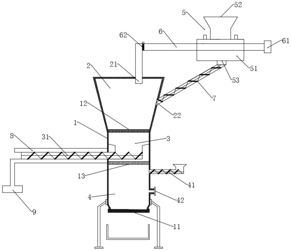
[0016] Such as figure 1 Shown is a polygeneration device for efficiently cleaning biomass and gas, comprising a furnace body 1, the bottom of the furnace body 1 is provided with an ash outlet 11, and the furnace body 1 is provided with a fire grate 12, and the fire grate 12 A heat conducting plate 13 is provided below;

[0017] Wherein, the top of the grate 12 is set as the gasification chamber 2, the carbonization chamber 3 is set between the grate 12 and the heat conduction plate 13, and the combustion chamber 4 is set below the heat conduction plate 13;

[001...


PUM


Abstract

The invention relates to a biomass efficient clean charcoal and gas poly-generation device which comprises a furnace body. An ash outlet is formed in the bottom of the furnace body, a fire grate is arranged in the furnace body, and a heat conducting plate is arranged below the fire grate. A gasification chamber is arranged above the fire grate, a carbonization chamber is arranged between the fire grate and the heat conducting plate, and a combustion chamber is arranged below the heat conducting plate. A feeding auger and a gas inlet are arranged on the side wall of the combustion chamber. An automatic charcoal discharging device is arranged in the carbonization chamber and above and close to the heat conducting plate. A gas outlet is formed in the top of the gasification chamber, and a first material inlet is formed in the side wall of the gasification chamber. According to the invention, a heat graded utilization principle is adopted, high heat generated by combustion in the combustion chamber can firstly carbonize biomass at the bottom of the fire grate, and meanwhile, residual heat can carry out oxidation-reduction reaction on materials entering the gasification chamber at the upper layer, so that biomass gas is generated. Therefore, the defect that the existing fixed bed updraft and downdraft gasifiers only produce biomass gas or charcoal is overcome, the co-production of biomass gas and charcoal is realized, and the utilization rate of biomass is greatly improved.

Description

technical field [0001] The invention belongs to the technical field of biomass energy utilization, in particular to the field of using biomass to prepare gas and charcoal. Background technique [0002] Energy and environmental issues have become the focus of global attention. With the rapid growth of energy consumption in China, the extensive use of fossil fuels has brought serious environmental pollution and ecological damage. Coal, oil, and natural gas are the main energy sources at this stage. Valuable organic chemical raw materials, the amount of resources is decreasing day by day, and the way that our country is generally used as fuel has caused a lot of waste. The development of clean renewable energy has become an urgent need for sustainable development. Among the renewable energy, it is the only clean energy that can be stored and transported on the earth. It has a large amount of resources, a wide distribution, and a huge development potential. Biomass gasification ...

Claims


Application Information

Patent Timeline
Patent Type & Authority Applications(China)
IPC IPC(8): C10J3/64C10J3/72C10J3/76C10J3/84
CPCC10J3/64C10J3/72C10J3/76C10J3/84C10J2300/0916C10J2200/15C10J2300/0909C10J2300/1223
Inventor 马培勇雷阳阳祁风雷邢献军夏永昭仰科孙海韵
Owner HEFEI UNIV OF TECH
Why Eureka
Try Eureka