Dyeing and drying device for chemical fiber production

A technology of drying device and chemical fiber yarn, which is applied in the field of dyeing, can solve the problems of no direct treatment of water vapor, the impact of working environment, and rheumatism of workshop personnel, and achieve the effects of reducing manual participation, reducing waste costs, and saving time

Inactive Publication Date: 2021-11-05
厦门淼凝贸易有限公司
View PDF0 Cites 0 Cited by
  • Summary
  • Abstract
  • Description
  • Claims
  • Application Information

AI Technical Summary

Problems solved by technology

[0002] At present, the dyeing of chemical fiber yarns involves a lot of waste of dyes, which increases the cost of subsequent processing of dyes, and it is not easy to store dyes, just because the use of dyes and the cost of later stages are more expensive. Secondly, the dyeing of chemical fiber yarns requires manual participation. , it is likely to cause uneven dyeing. The integrated machine for drying chemical fiber yarn is too large, and the water vapor from drying is not directly processed, and it is scattered in the production workshop, which affects the working environment and easily causes rheumatism and overheating to the workshop personnel. Phenomena such as heat stroke are not conducive to human health

Method used


Image

  • Dyeing and drying device for chemical fiber production
  • Dyeing and drying device for chemical fiber production
  • Dyeing and drying device for chemical fiber production

Examples


Embodiment Construction

[0021] In order to make the purpose and advantages of the present invention clearer, the present invention will be described in detail below in conjunction with the examples. It should be understood that the following words are only used to describe a kind of dyeing and drying device for chemical fiber production of the present invention or several specific ones. Embodiments do not strictly limit the protection scope of the specific claims of the present invention. As used herein, the terms up, down and left and right are not limited to their strict geometric definitions, but include reasonable and inconsistent tolerances for machining or human errors. The specific characteristics of the dyeing and drying device for the production of chemical fiber filaments are described in detail below:

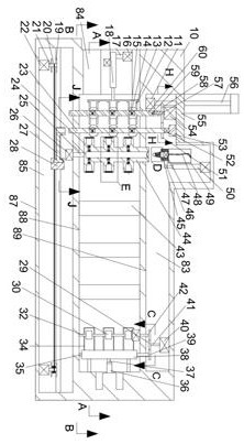
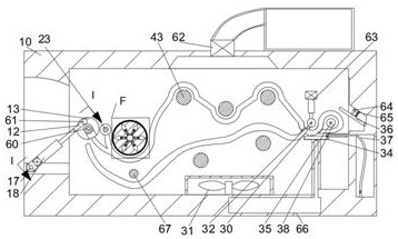
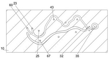
[0022] refer to Figure 1-11 According to an embodiment of the present invention, a dyeing and drying device for the production of chemical fiber filaments includes a casing 10, a control c...


PUM


Abstract

The invention discloses a dyeing and drying device for chemical fiber production. The device comprises a machine shell; a control cavity is arranged in the machine shell; a loading cavity communicated with the outside is arranged in the lower end wall of the control cavity; a moving cavity is arranged in the lower end wall of the loading cavity; six centrifugal cavities are arranged in a dyeing wheel; two one-way doors are arranged on a track; a moving mechanism comprises a sliding groove rod slidably connected to the rear end wall of the moving cavity; the sliding groove rod can move left and right; an executing mechanism comprises a pushing block arranged in a centrifugal cavity; the pushing block can push a flow control ball under the action of centrifugal force to enable a coloring agent to flow out; a control mechanism comprises a lead screw motor fixedly connected to the lower end wall of the control cavity; the lead screw motor is in power connection with a lead screw, and the other end of the lead screw is rotationally connected with the machine shell outside; a moving block is slidably connected to the lead screw; and the lead screw controls the moving block to move up and down.

Description

technical field [0001] The invention relates to the technical field of dyeing, in particular to a dyeing and drying device for chemical fiber production. Background technique [0002] At present, the dyeing of chemical fiber threads involves a lot of waste of dyestuffs, which increases the cost of subsequent processing of dyestuffs, and it is not easy to store dyestuffs, just because the use of dyestuffs and later costs are more. Secondly, the dyeing of chemical fiber threads requires manual participation. , it is likely to cause uneven dyeing. The integrated machine for drying chemical fiber yarn is too large, and the water vapor from drying is not directly processed, and it is scattered in the production workshop, which affects the working environment and easily causes rheumatism and overheating to the workshop personnel. Phenomena such as heat stroke are not conducive to people's health. Contents of the invention [0003] The object of the present invention is to provi...

Claims


Application Information

Patent Timeline
Patent Type & Authority Applications(China)
IPC IPC(8): D06B1/12D06B15/00D06B23/04D06B3/04D06B23/20
Inventor 程玮
Owner 厦门淼凝贸易有限公司
Why Eureka
Try Eureka