Light well point combined type foundation pit dewatering device
A light-duty well point, combined technology, applied in water supply installations, drinking water installations, infrastructure projects, etc., can solve the problems of difficult construction, inconvenient operation, etc., to facilitate construction, reduce the possibility of dust, and save manpower Effect
- Summary
- Abstract
- Description
- Claims
- Application Information
AI Technical Summary
Problems solved by technology
Method used
Image

Examples
Embodiment Construction
[0034] The following is attached Figure 1-6 The application is described in further detail.
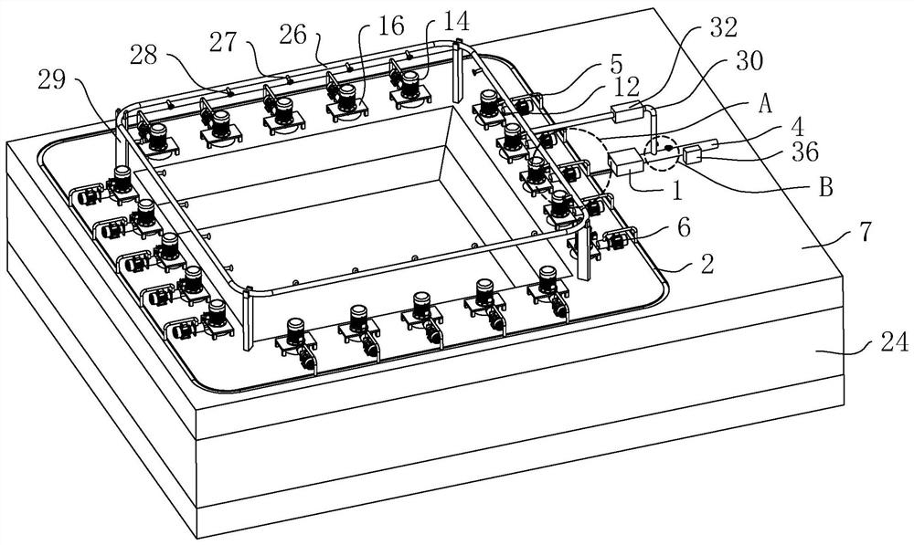
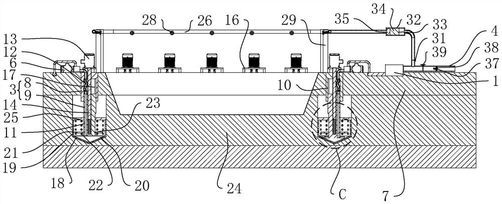
[0035] The embodiment of the application discloses a light well point combined foundation pit dewatering device. refer to figure 1 and figure 2 , a light well point combined foundation pit dewatering device includes a vacuum jet pump 1, a water collection main pipe 2, a well point pipe 3, a drainage pipe 4, a curved connecting pipe 5 and a deep suction high pressure jet pump 6. The water collection main pipe 2 is laid on the ground 7 in the form of a sealing ring, the vacuum jet pump 1 communicates with the water collection main pipe 2 through the outlet pipe, and one end of the vacuum jet pump 1 communicates with the drain pipe 4 .
[0036] refer to figure 1 and figure 2 , One end of the curved connecting pipe 5 communicates with the water collecting main pipe 2, and the other end communicates with the well point pipe 3. A plurality of well point pipes 3 are provided, and the ...
PUM
 Abstract
Description
Claims
Application Information
 - Generate Ideas
- Intellectual Property
- Life Sciences
- Materials
- Tech Scout
- Unparalleled Data Quality
- Higher Quality Content
- 60% Fewer Hallucinations
Browse by: Latest US Patents, China's latest patents, Technical Efficacy Thesaurus, Application Domain, Technology Topic, Popular Technical Reports.
© 2025 PatSnap. All rights reserved.Legal|Privacy policy|Modern Slavery Act Transparency Statement|Sitemap|About US| Contact US: help@patsnap.com