
Household garbage combustion furnace

A technology for domestic waste and incinerators, which is applied in the direction of combustion methods, combustion types, incinerators, etc., can solve problems that affect the efficiency of waste incineration work, high requirements for driving equipment, and incomplete garbage incineration, etc., to reduce occupied space, Avoid garbage slipping and low power requirements

Pending Publication Date: 2021-11-05
代卓莹
View PDF0 Cites 0 Cited by
  • Summary
  • Abstract
  • Description
  • Claims
  • Application Information

AI Technical Summary

Problems solved by technology

[0003] Common household waste incineration furnaces include vertical and horizontal types, which can burn garbage and fully treat exhaust gas. Horizontal incinerators can improve combustion efficiency by turning them over. However, existing horizontal incinerators generally use the entire furnace body to Turning over to realize the flipping of garbage requires high requirements for driving equipment and a large driving force, resulting in high equipment costs and a large footprint
Moreover, the furnace body of the existing horizontal combustion furnace is inclined, and the garbage will gradually slide down in the furnace body, and sometimes it is easy for the garbage to slide out without burning completely, resulting in incomplete combustion of the garbage and affecting the efficiency of the garbage burning work. work efficiency

Method used


Image

  • Household garbage combustion furnace
  • Household garbage combustion furnace
  • Household garbage combustion furnace

Examples


Embodiment Construction

[0020] The following will clearly and completely describe the technical solutions in the embodiments of the present invention with reference to the accompanying drawings in the embodiments of the present invention. Obviously, the described embodiments are only some, not all, embodiments of the present invention. Based on the embodiments of the present invention, all other embodiments obtained by persons of ordinary skill in the art without making creative efforts belong to the protection scope of the present invention.

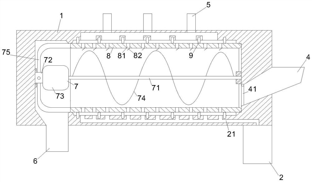
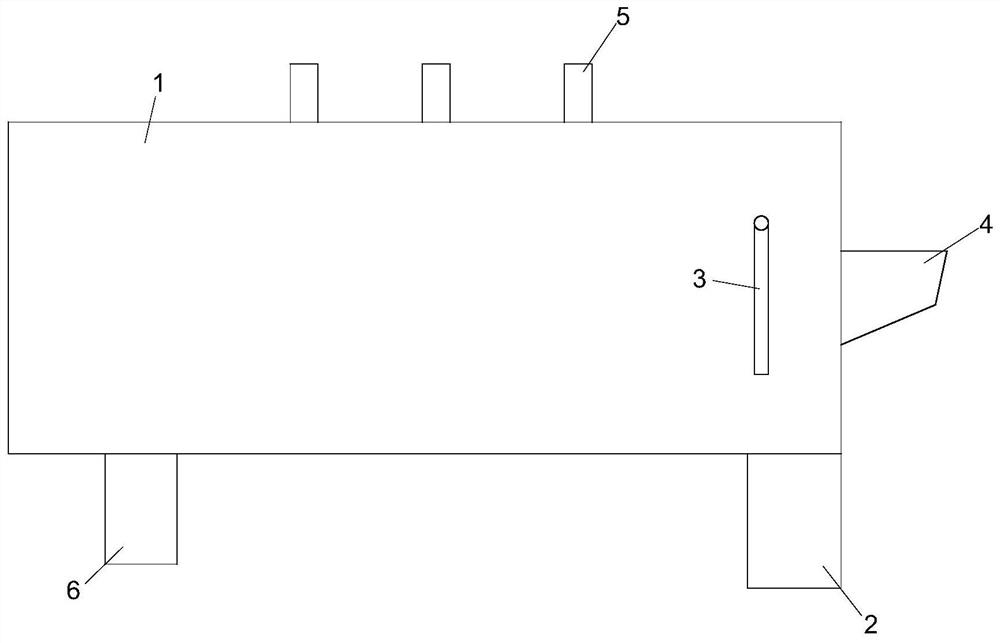
[0021] like Figure 1 to Figure 3 As shown, the present invention provides a domestic waste combustion furnace, comprising a furnace body 1, the upper outer surface of the furnace body 1 is provided with an exhaust port 5, the front end outer surface of the furnace body 1 is provided with an ignition gun 3, and the right side of the furnace body 1 The surface is provided with a feed port 4, the lower end of the furnace body 1 is provided with a discharge port ...


PUM


Abstract

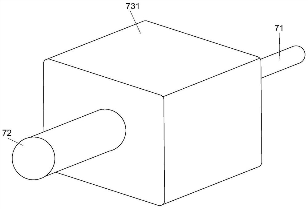
The invention relates to the technical field of garbage treatment, in particular to a household garbage combustion furnace. The household garbage combustion furnace comprises a furnace body, an exhaust port is formed in the outer surface of the upper end of the furnace body, an ignition gun is arranged on the outer surface of the front end of the furnace body, a feeding port is formed in the right side face of the furnace body, a discharging port is formed in the portion, close to the left side, of the lower end of the furnace body, an air blower is arranged on the portion, close to the right side, of the lower end of the furnace body, an overturning cylinder is arranged in the furnace body, a plurality of pulleys are uniformly arranged on the inner wall of the furnace body, the pulleys are in contact with the outer wall of the overturning cylinder, a stirring device is arranged on the center line of the overturning cylinder, and the left side and the right side of the stirring device are rotationally connected with the centers of the inner walls of the left side and the right side of the furnace body correspondingly. A horizontal combustion furnace is arranged, the overturning barrel is arranged in the furnace body to overturn garbage, meanwhile, spiral blades are arranged to controllably convey the garbage, the occupied space of the equipment is reduced, the power requirement is lower, the garbage is prevented from sliding down, the garbage combustion sufficiency is remarkably improved, and then the working efficiency is improved.

Description

technical field [0001] The invention relates to the technical field of garbage treatment, in particular to a domestic garbage combustion furnace. Background technique [0002] Garbage disposal has always been a major environmental issue of concern to the world. The traditional garbage disposal methods mainly include landfill and combustion. Landfilling will take up a lot of valuable land resources, and some wastes take a long time to degrade naturally, so they are not suitable for landfilling. Garbage burning is still the main way to deal with garbage. Through burning, not only can the volume of garbage be greatly reduced, but also the heat generated by burning can be used for heating and so on. At this stage, garbage incineration is basically completed through garbage incineration furnaces, and garbage incinerators are still an indispensable device for garbage disposal. [0003] Common household waste incinerators include vertical and horizontal types, which can burn garb...

Claims


Application Information

Patent Timeline
IPC IPC(8): F23G5/20F23G5/44
CPCF23G5/20F23G5/444F23G2203/20F23G2205/121
Inventor 代卓莹李周滔
Owner 代卓莹
Learn More