Hydrogen fuel cell waste heat utilization system

A technology of fuel cells and fuel cell stacks, applied in the direction of fuel cell heat exchange, fuel cells, fuel cell additives, etc., can solve the problem of low energy efficiency of hydrogen fuel cells, limited ship space, and inability to install large-scale air-cooled equipment, etc. question

Pending Publication Date: 2021-11-05
上海杰宁新能源科技发展有限公司
View PDF0 Cites 1 Cited by
  • Summary
  • Abstract
  • Description
  • Claims
  • Application Information

AI Technical Summary

Problems solved by technology

However, when applied on ships, due to the limited space of ships, it is impossible to install large-scale air-cooled equipment, which leads to the low energy efficiency of hydrogen fuel cells applied on ships

Method used


Image

  • Hydrogen fuel cell waste heat utilization system
  • Hydrogen fuel cell waste heat utilization system

Examples


Embodiment 1

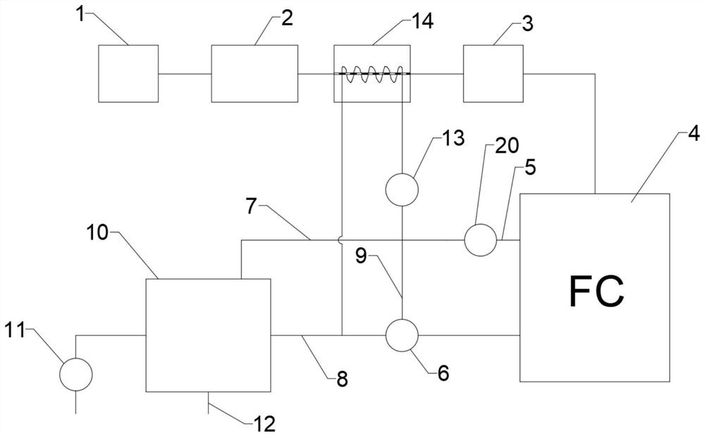
[0038] figure 1 It is a schematic diagram of the overall structure of the hydrogen fuel cell waste heat utilization system in Embodiment 1 of the present invention.

[0039] Such as figure 1 As shown, the hydrogen fuel cell waste heat utilization system provided by the embodiment of the present invention includes: a hydrogen storage tank 1, a gasification device 2, a pressurizing device 3, a fuel cell stack 4, a three-way solenoid valve 6, a first pipeline 5, The second pipeline 7, the third pipeline 9, the fourth pipeline 8, the first heat exchanger 10, the water pump 11, the fifth pipeline 12, the circulation pump 20 and the controller.

[0040]Wherein, the hydrogen storage tank 1 belongs to the prior art and is used for storing liquid hydrogen. The outlet of the hydrogen storage tank 1 communicates with the inlet of the gasification device 2 . The function of the gasification device 2 is to expand and vaporize the hydrogen gas coming out of the hydrogen storage tank 1, s...

Embodiment 2

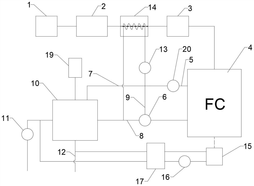
[0059] figure 2 It is a schematic diagram of the overall structure of the hydrogen fuel cell waste heat utilization system in Embodiment 2 of the present invention.

[0060] Such as figure 2 As shown, on the basis of the first embodiment, the hydrogen fuel cell waste heat utilization system provided by the embodiment of the present invention further includes: a heat dissipation device.

[0061] The output end of the fuel cell is provided with a DC-DC converter 15 . The DC-DC converter 15 will generate a certain amount of waste heat during operation.

[0062] The cooling device includes: a second auxiliary pump 16 and a third heat exchanger 17 .

[0063] The third heat exchanger 17 is arranged on the DC-DC converter 15, the second auxiliary pump 16 is connected in series on the heat exchange circuit between the third heat exchanger 17 and the DC-DC converter 15, the second auxiliary The pump 16 is electrically connected to the controller, the condensed water inlet of the ...


PUM


Abstract

The embodiment of the invention discloses a hydrogen fuel cell waste heat utilization system. The hydrogen fuel cell waste heat utilization system comprises a hydrogen storage tank, a gasification device, a pressurization device, a fuel cell pack, a three-way electromagnetic valve, a first pipeline, a second pipeline, a third pipeline, a fourth pipeline, a first heat exchanger, a water drawing pump, a fifth pipeline, a circulating pump and a controller. An outlet of the hydrogen storage tank is communicated with an inlet of the gasification device, an outlet of the gasification device is communicated with an inlet of the pressurizing device, and an outlet of the pressurizing device is communicated with a gas inlet of the fuel battery pack; a water outlet of the fuel battery pack is communicated with the first pipeline, and the first pipeline is communicated with a water inlet of the three-way electromagnetic valve. The hydrogen fuel cell waste heat utilization system can effectively utilize the space on a ship, a hydrogen fuel cell is cooled by cooling water, and the energy efficiency of the hydrogen fuel cell is improved.

Description

technical field [0001] Embodiments of the present invention relate to the field of clean energy technology, and in particular to a hydrogen fuel cell waste heat utilization system. Background technique [0002] A hydrogen fuel cell is an energy conversion device that uses the chemical energy of hydrogen and oxygen in the air to produce electrical energy. Hydrogen fuel cells have the advantages of high conversion efficiency, large capacity, and high specific energy. The application of hydrogen fuel cells on ships as a source of electrical energy has great advantages, such as good mute effect, high work efficiency, and no pollution. However, at present, hydrogen fuel cells will generate a large amount of waste heat during operation. For this part of waste heat, the common practice is to dissipate heat through air cooling equipment. However, when it is applied on a ship, due to the limited space of the ship, it is impossible to install large-scale air cooling equipment, which...

Claims


Application Information

Patent Timeline
IPC IPC(8): H01M8/04007H01M8/04276H01M8/04082H01M8/04029H01M8/04701H01M8/04089
CPCH01M8/04097H01M8/04201H01M8/04029H01M8/04074H01M8/04723H01M8/04276Y02E60/50Y02P70/50
Inventor 赵龙董佳怡王智慧
Owner 上海杰宁新能源科技发展有限公司
Why Eureka
Try Eureka