Receiver radio frequency link nonlinear effect multi-parameter test platform

A non-linear effect, radio frequency link technology, applied in the field of multi-parameter test platform of receiver radio frequency link nonlinear effect, can solve the problems of large data error, large error, repeatability and intersection of test data, etc. Effect

Active Publication Date: 2021-11-05
SHANDONG UNIV
View PDF6 Cites 2 Cited by
  • Summary
  • Abstract
  • Description
  • Claims
  • Application Information

AI Technical Summary

Problems solved by technology

[0005] For passive intermodulation test equipment, there are currently relevant equipment for testing one or several parameters and instruments, but there is no comprehensive multi-parameter and comprehensive test platform for comprehensive nonlinear effects.
At present, the comprehensive test platform for the nonlinear effect of the radio frequency link of the receiver is still in a blank state. During the nonlinear research, a test platform is temporarily built, and the test results are applied to other research and applications of the receiver link. Due to the electromagnetic environment As well as different conditions such as temperature in different application scenarios, the error of a test result in future applications is very large
[0006] In addition, the ubiquitous test platform instruments for receiver links are currently blank. The current test instruments are mainly used to test certain link parameters, and the test instruments that cover almost all response nonlinear effects have not yet appeared.
When it is necessary to test parameters related to nonlinear effects, building a temporary test platform according to the nature of the parameters is the current mainstream test method. When the test parameters change, the test platform will also be changed accordingly. Due to the different assembly environments, the test data often varies. Repeatability crossover, the data provided have large errors

Method used


Image

  • Receiver radio frequency link nonlinear effect multi-parameter test platform
  • Receiver radio frequency link nonlinear effect multi-parameter test platform
  • Receiver radio frequency link nonlinear effect multi-parameter test platform

Examples


Embodiment 1

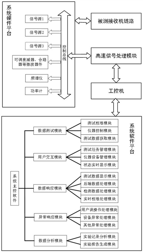
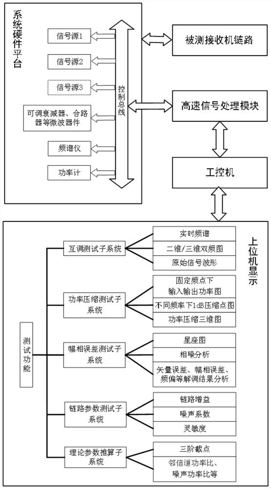
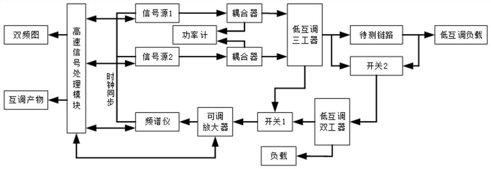
[0048] This embodiment comprehensively considers the universal test platform integrating multiple parameters, and the proposed overall test plan is composed of five parts: system software platform, receiver link under test, system hardware platform, high-speed signal processing module and industrial computer, based on Considering the actual work objectives, the test methods of each sub-test system of the test system can be shared in the RF signal generation part and the receiving analysis part, but there are differences in the type and number of signal sources input to the receiver link under test, so the multiple The test subsystems are integrated in a set of equipment, sharing a set of system software platform, system hardware platform, high-speed signal processing module and industrial computer. The design scheme of the test system has accurate test results, standardized test process, and friendly human-computer interaction. The specific structure is as follows: figure 1 sh...


PUM


Abstract

The invention discloses a receiver radio frequency link nonlinear effect multi-parameter test platform which comprises a plurality of test modules such as an intermodulation test subsystem, a power compression test subsystem, an amplitude-phase error test subsystem, a receiver link parameter test subsystem and a theoretical parameter calculation test subsystem. The testing and the displaying of a dual-frequency image, an input and output power response diagram under a fixed frequency point, a 1dB compression point diagram under different frequency points, a power compression three-dimensional diagram, an error vector amplitude, an amplitude-frequency characteristic diagram, a phase-frequency characteristic diagram, a nonlinear effect parameter, a third-order truncation point and an adjacent channel power ratio are realized; The test platform is a universal comprehensive test platform scheme aiming at the nonlinear effect of the radio frequency link of the receiver, and can be suitable for testing the nonlinear effect of various types and frequency bands of receivers between 150MHz and 40GHz.

Description

technical field [0001] The invention relates to the technical field of receiver radio frequency link testing, in particular to a receiver radio frequency link nonlinear effect multi-parameter test platform. Background technique [0002] The statements in this section merely provide background information related to the present invention and do not necessarily constitute prior art. [0003] The passive intermodulation product has a threshold effect, and the intermodulation product does not appear when the input level does not reach the threshold value, but when the power level reaches or exceeds a certain threshold value, the passive intermodulation product will appear. Passive intermodulation products change with time, are unstable in time, and are also very sensitive to temperature. In order to obtain more reliable data, long-term observations under various test conditions are required. [0004] There are mainly five methods for testing intermodulation products: transmissi...

Claims


Application Information

Patent Timeline
Patent Type & Authority Applications(China)
IPC IPC(8): H04B17/29
CPCH04B17/29
Inventor 严发宝于永林尚自乾张磊陈耀
Owner SHANDONG UNIV
Why Eureka
Try Eureka