
Shaft seal system, turbomachine with shaft seal system, and method of sealing a shaft

A shaft seal and machine technology, applied in the field of exhaust turbochargers, can solve the problems of bearing housing pumping effect and oil leakage, and achieve the effect of avoiding wear

Pending Publication Date: 2021-11-05
TURBO SYST SWITZERLAND LTD
View PDF5 Cites 0 Cited by
  • Summary
  • Abstract
  • Description
  • Claims
  • Application Information

AI Technical Summary

Problems solved by technology

It has been found that conventional shaft sealing systems have the problem that oil leakage can occur at rest and at low speeds because there is a very small positive or even negative pressure drop, creating a "pumping effect" on the bearing housing

Method used


Image

  • Shaft seal system, turbomachine with shaft seal system, and method of sealing a shaft
  • Shaft seal system, turbomachine with shaft seal system, and method of sealing a shaft
  • Shaft seal system, turbomachine with shaft seal system, and method of sealing a shaft

Examples


Embodiment Construction

[0018] Reference will now be made in detail to the various embodiments, one or more examples of which are illustrated in each figure. Each example is provided by way of explanation, not limitation. For example, features illustrated or described as part of one embodiment can be used on or in conjunction with any other embodiment to yield a still further embodiment. The present disclosure is intended to cover such modifications and variations.

[0019] In the following description of the drawings, the same reference numerals refer to the same or similar components. Generally, only differences with respect to individual embodiments are described. Unless otherwise specified, descriptions of parts or aspects in one embodiment are also applicable to corresponding parts or aspects in another embodiment.

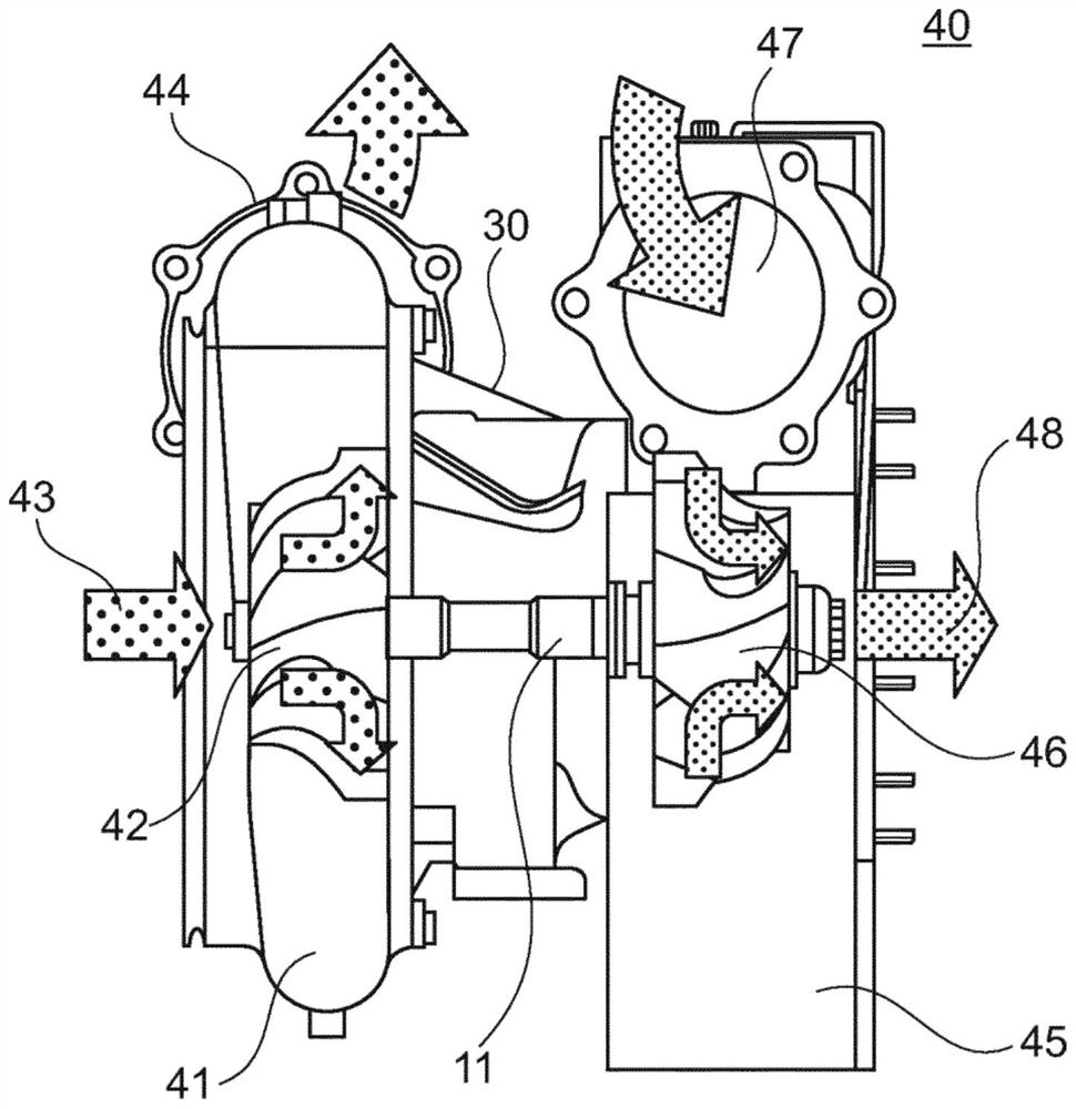
[0020] Exemplary reference figure 1 , depicts an exhaust-gas turbocharger 40 with a radial compressor 41 and a radial turbine 45 according to the prior art. In particular, the ...


PUM


Abstract

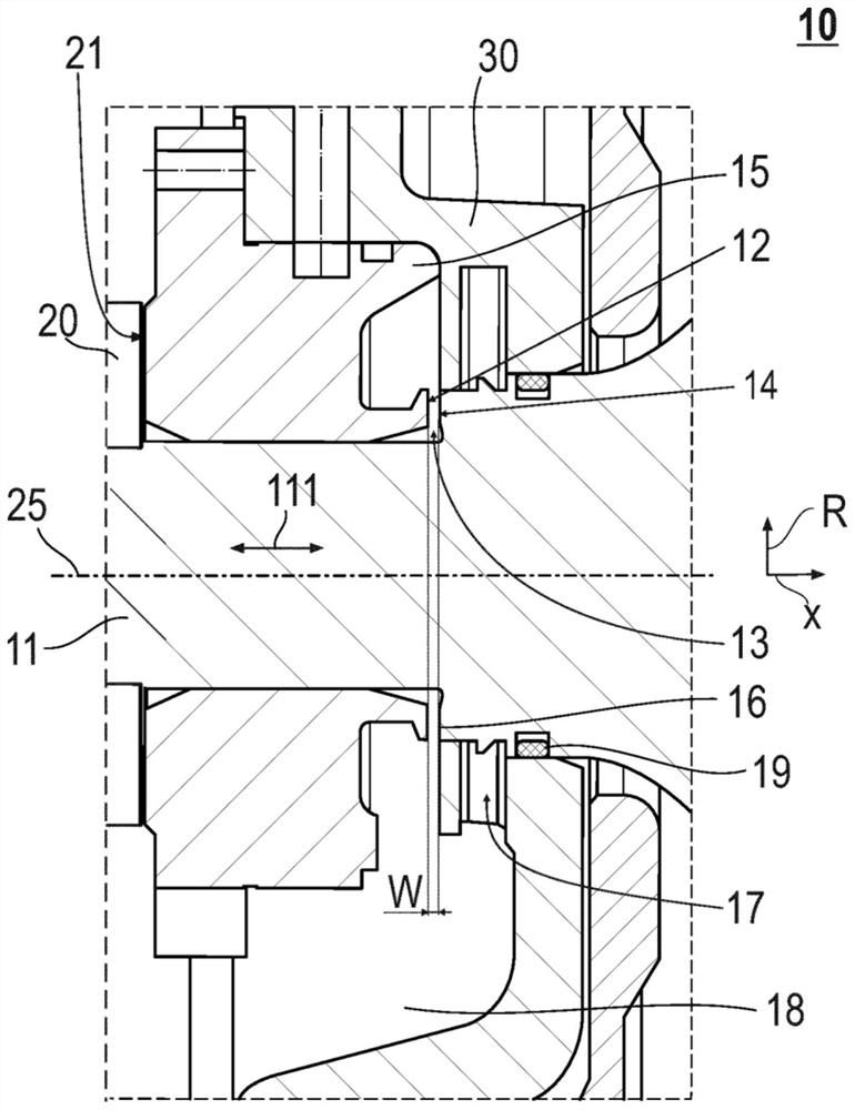
A shaft seal system (10) of a shaft (11) supported in a bearing housing (30) of a turbomachine is described. The shaft seal system includes a rotor-side seal (19) arranged between the bearing housing (30) and the shaft (11). Additionally, the shaft seal system includes an axial bearing (15) supporting the shaft (11). Further, a gap (13) is provided between a rotor-side thrust bearing surface (12) of the axial bearing (15) and an opposite surface (14) of the shaft (11). A gap width (W) of the gap (13) is adjustable as a function of rotation speed of the shaft (11).

Description

technical field [0001] Embodiments of the present disclosure relate to shaft sealing systems for turbomachines, in particular exhaust turbochargers. Other embodiments of the present disclosure relate to methods of sealing a shaft, particularly a shaft supported in a bearing housing of a turbomachine. Background technique [0002] Turbomachines (including, for example, turbochargers or power turbines) transfer energy between a rotor and a fluid. For example, an exhaust-gas turbocharger includes a compressor for transferring energy from a rotor to a fluid and a turbine for transferring energy from the fluid to the rotor. [0003] Exhaust-gas turbochargers are known for increasing the power of internal combustion engines. In an exhaust-gas turbocharger, a turbine is arranged in the exhaust path of the internal combustion engine and a compressor is arranged upstream of the internal combustion engine, the compressors being connected to the turbine by a common shaft. An exhaust...

Claims


Application Information

Patent Timeline
Patent Type & Authority Applications(China)
IPC IPC(8): F01D25/16F16C17/04
CPCF01D25/168F05D2220/40F05D2240/52F16C17/04F01D25/16F01D25/183F05D2220/30F05D2240/55F05D2260/98F16J15/162
Inventor 托马斯·雷钦马赛厄斯·里奇纳
Owner TURBO SYST SWITZERLAND LTD
Learn More