
Rotating electrical machine, electric motor, vehicle having an electric drive, can and production method for same

a technology of electric motors and electric motors, which is applied in the direction of dynamo-electric machines, electrical devices, supports/enclosements/casings, etc., can solve the problems of reducing efficiency, heating of winding heads, and effective system limits of usable motors, so as to increase the gap width and reduce efficiency

Pending Publication Date: 2021-07-15
MAGNA POWERTRAIN AG & CO KG
View PDF0 Cites 0 Cited by
  • Summary
  • Abstract
  • Description
  • Claims
  • Application Information

AI Technical Summary

Benefits of technology

The invention aims to improve the efficiency of electric machines and the cooling of stator components, particularly the winding heads. The invention is implemented through the use of a tube formed with ferrite material, which is placed in the gap between the stator and rotor. The tube helps to fill the gap with magnetically permeable material, reducing the gap width and improving cooling without compromising efficiency. The covers of the electric machine can be made with thermoplastic or thermoset materials, and the ferrite material can be mixed with a carrier material, such as thermoplastic, before being formed into the shape of the can.

Problems solved by technology

During operation, even electric motors generate waste heat.
The problem of winding heads heating up arises in particular in the operating range of relatively high continuous loads or in the case of high peak loads.
This then in fact often forms the effective system limit for the usable motor power in the case of present designs.
A disadvantage of this construction is that the oil causes a drag torque (braking torque) for the motor, and the efficiency thereof thus decreases.
A disadvantage of known canned motors is that they have a considerably widened air gap between stator and rotor in order to be able to accommodate the can therein.
This is detrimental to the magnetic coupling between stator and rotor and thus to the efficiency.

Method used


Image

  • Rotating electrical machine, electric motor, vehicle having an electric drive, can and production method for same
  • Rotating electrical machine, electric motor, vehicle having an electric drive, can and production method for same
  • Rotating electrical machine, electric motor, vehicle having an electric drive, can and production method for same

Examples


Embodiment Construction

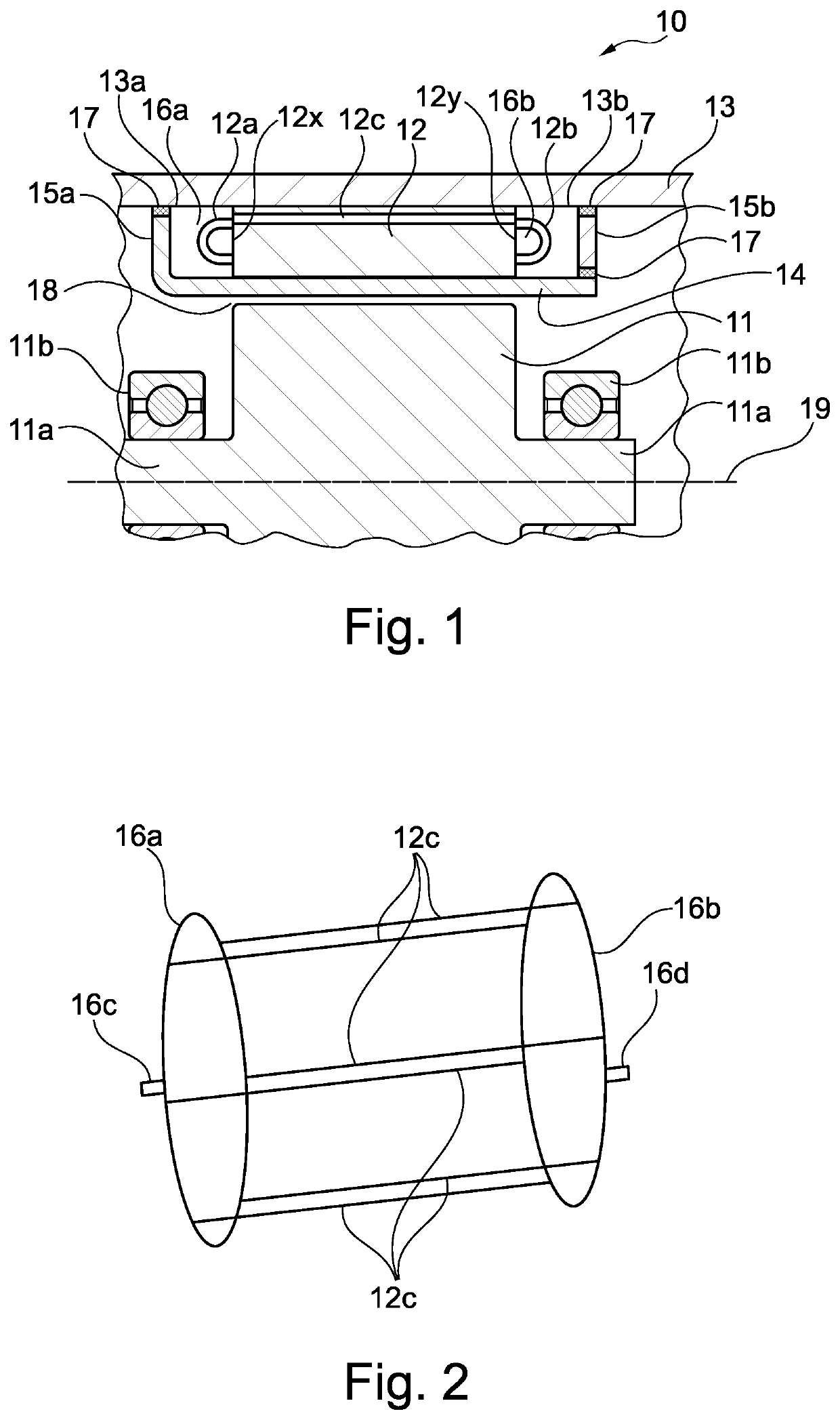
[0036]FIG. 1 shows a highly schematic section through a rotating electric machine, for example an electric motor. The axis of rotation 19 of the electric machine lies in the section plane. Only the upper half of the structure is shown. The half below the axis of rotation 19 may be substantially mirror-symmetrical with respect thereto, and is therefore not illustrated. 11 is the rotor of the motor, which is mounted so as to be rotatable about a shaft 11a, for example by ball bearings 11b. 19 is the axis of rotation of the rotor. 12 is the stator of the machine. In the embodiment shown, said stator is situated radially outside the rotor 11.

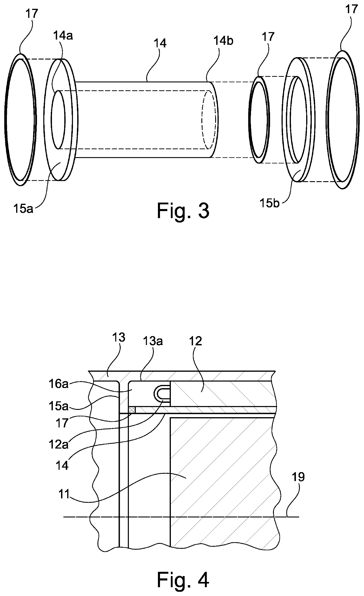
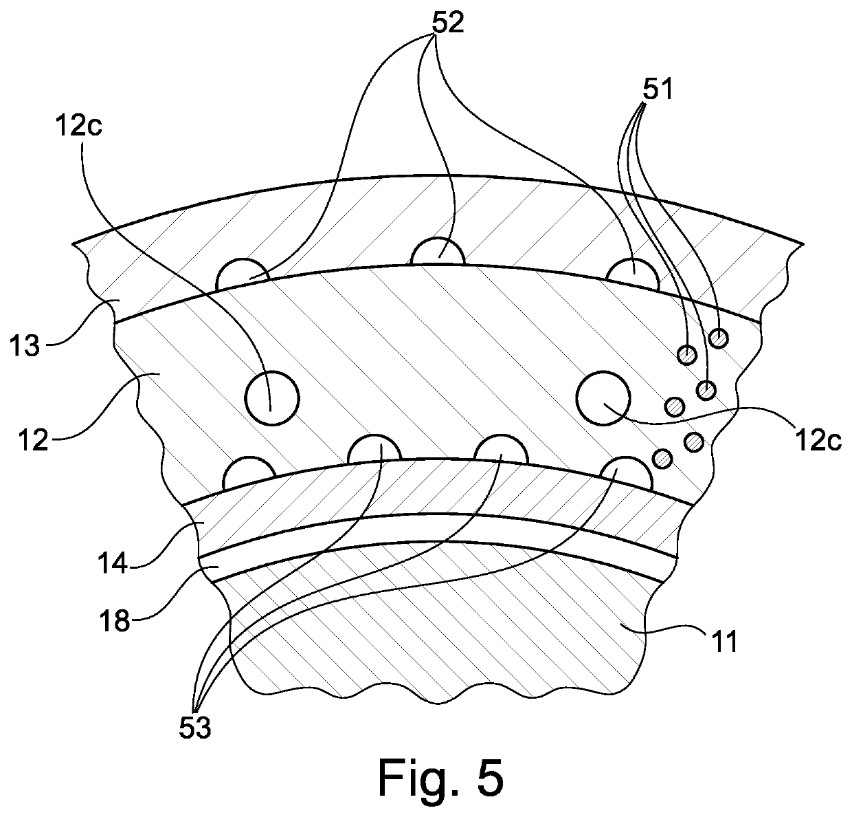
[0037]In general, stators are constructed, on the one hand, from iron components and, on the other hand, from winding lines, which is not illustrated in detail in FIG. 1 but is indicated in FIG. 5. The iron components are commonly laminated cores which are stacked one on top of the other (stacking direction in the direction of the axis 19). The lami...


PUM


Abstract

An electric machine has a rotor, a stator which is spaced apart from the rotor in a radial direction by a gap and which has one or more stator windings and winding heads at one or both axial ends of the stator, in the gap a tube with a fluid-tight wall which extends in an axial direction and in a circumferential direction and which has a wall thickness in a radial direction, wherein the tube extends in an axial direction beyond the winding heads of the stator at least one stator end, at least one cover, which extends radially and which covers the winding heads of the at least one axial end of the stator, at the at least one axial end of the tube, and a cooling fluid inlet and / or a cooling fluid outlet for a cooling fluid chamber which is closed by the tube and by the cover. At least regions of the tube are formed with a ferrite material.

Description

CROSS-REFERENCE TO RELATED APPLICATIONS[0001]This application is a National Stage of International Application No. PCT / EP2019 / 063108, filed May 21, 2019, which claims priority to DE102018209367.9, filed Jun. 12, 2018. The entire disclosures of each of the above applications are incorporated herein by reference.FIELD OF THE INVENTION[0002]The invention relates to a rotating electric machine, an electric motor, a vehicle with electric drive, a can and a production method for a can.[0003]Vehicles with electric drive have one or more electric motors which are fed from an energy source (often a battery). During operation, even electric motors generate waste heat. Said waste heat is generated in such quantities that it must be taken into consideration in the design and must be dissipated.[0004]The waste heat is also generated in the stator windings. Here, regions which are subject to particular high thermal load are often the winding heads, that is to say those parts of the winding lines ...

Claims


Application Information

Patent Timeline
Patent Type & Authority Applications(United States)
IPC IPC(8): H02K9/197H02K5/20H02K15/14
CPCH02K9/197H02K15/14H02K5/203H02K5/128
Inventor NESS, WERNER
Owner MAGNA POWERTRAIN AG & CO KG
Learn More