Petroleum separation device based on density separation method and separation method thereof

A density separation and separation device technology, applied in separation methods, filtration separation, liquid separation, etc., can solve the problems that affect the separation process, difficult to clean, slow layering speed, etc., to achieve the effect of ensuring separation accuracy and facilitating subsequent separation

Active Publication Date: 2021-11-09
江苏华普泰克石油装备有限公司
View PDF7 Cites 8 Cited by
  • Summary
  • Abstract
  • Description
  • Claims
  • Application Information

AI Technical Summary

Problems solved by technology

[0002] Oil extraction usually uses drilling methods to extract crude oil from the ground. The extracted oil is usually a mixture of oil, gas, water and sediment, so it needs to be separated to separate the oil from other impurities. The current separation method uses Density separation method, that is, through the different densities of oil, water and sediment, the oil is allowed to stand and stratify, and the gas overflows automatically, while the sediment is located in the bottom layer of the liquid, the water is in the middle layer, and the oil is in the top layer, and then the top layer is extracted However, the separation speed of the current separation device is slow, and it is easy to absorb the water layer in the middle when extracting the oil layer, and it is difficult to clean the bottom sediment layer, which affects the subsequent separation process. Therefore, we propose a Oil separation device and separation method based on density separation method are used to solve the above problems

Method used


Image

  • Petroleum separation device based on density separation method and separation method thereof
  • Petroleum separation device based on density separation method and separation method thereof
  • Petroleum separation device based on density separation method and separation method thereof

Examples


Embodiment Construction

[0027] The following will clearly and completely describe the technical solutions in the embodiments of the present invention with reference to the accompanying drawings in the embodiments of the present invention. Obviously, the described embodiments are only some of the embodiments of the present invention, not all of them. Based on the embodiments of the present invention, all other embodiments obtained by persons of ordinary skill in the art without making creative efforts belong to the protection scope of the present invention.

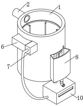
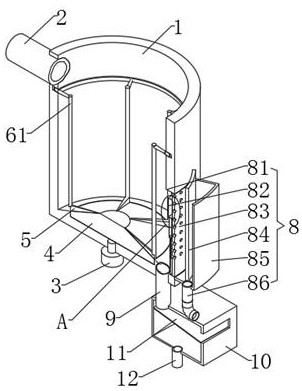
[0028] see Figure 1-Figure 5, the present invention provides a technical solution: an oil separation device based on the density separation method, comprising a centrifugal bucket 1, the top of one side of the centrifugal bucket 1 is fixedly sleeved with an oil delivery pipe 2, and the bottom of the inner cavity of the centrifugal bucket 1 is rotated and sleeved with a turntable 4, A motor 3 is fixedly installed on the bottom surface of the cent...


PUM


Abstract

The invention discloses a petroleum separation device based on a density separation method and a separation method of the petroleum separation device, and belongs to the technical field of petroleum exploitation. The petroleum separation device comprises a centrifugal barrel, the top of the centrifugal barrel is sleeved with a petroleum conveying pipe, and the bottom of the centrifugal barrel is sleeved with a rotating disc; a motor is arranged on the bottom surface of the centrifugal barrel, the motor is connected with the rotating disc, and a plurality of blades are arranged on the top surface of the rotating disc; a transmission mechanism is arranged between the top surfaces of the blades and the centrifugal barrel, the transmission mechanism is connected with a flushing mechanism, an oil collecting mechanism is arranged at the bottom of the centrifugal barrel, a bottom plate of the centrifugal barrel is sleeved with one end of a slag discharging pipe, the other end of the slag discharging pipe is sleeved with the top of one side of a water collecting tank, a filter plate is arranged in the water collecting tank, and a water discharging pipe is fixedly sleeved with the bottom of the water collecting tank. Petroleum enters the centrifugal barrel after being extracted, gas discharge and layering speed are accelerated through rotary centrifugation of the rotating disc, then an oil layer flows out through the oil collecting mechanism, a sediment layer and a water layer are discharged through the slag discharging pipe, the discharged water layer repeatedly flushes the centrifugal barrel through the transmission mechanism and the flushing mechanism, and self-cleaning is achieved.

Description

technical field [0001] The invention relates to the technical field of oil exploitation, in particular to an oil separation device based on a density separation method and a separation method thereof. Background technique [0002] Oil extraction usually uses drilling methods to extract crude oil from the ground. The extracted oil is usually a mixture of oil, gas, water and sediment, so it needs to be separated to separate the oil from other impurities. The current separation method uses Density separation method, that is, through the different densities of oil, water and sediment, the oil is allowed to stand and stratify, and the gas overflows automatically, while the sediment is located in the bottom layer of the liquid, the water is in the middle layer, and the oil is in the top layer, and then the top layer is extracted However, the separation speed of the current separation device is slow, and it is easy to absorb the water layer in the middle when extracting the oil lay...

Claims


Application Information

Patent Timeline
Patent Type & Authority Applications(China)
IPC IPC(8): B01D19/00B01D17/025B01D36/04
CPCB01D19/0042B01D17/0211B01D36/045
Inventor 叶子华李荣
Owner 江苏华普泰克石油装备有限公司
Why Eureka
Try Eureka