Self-adaptive clamping mechanism of numerically controlled lathe

A self-adaptive, clamping mechanism technology, applied in the field of machine tools, can solve problems such as inability to cut shaft workpieces, inability to rotate the spindle, and low clamping accuracy.

Active Publication Date: 2021-11-09
浙江迈兴途智能装备股份有限公司
View PDF8 Cites 0 Cited by
  • Summary
  • Abstract
  • Description
  • Claims
  • Application Information

AI Technical Summary

Problems solved by technology

[0003] The Chinese patent with the application number CN202010762778.1 discloses a spindle-loading CNC machine tool, which uses a cylinder and a one-way limit structure to realize the movement and clamping of the workpiece. It is not difficult to see that its clamping accuracy is low, and The main shaft cannot rotate, it can only be used for cutting pipe workpieces, not for cutting shaft workpieces

Method used


Image

  • Self-adaptive clamping mechanism of numerically controlled lathe
  • Self-adaptive clamping mechanism of numerically controlled lathe
  • Self-adaptive clamping mechanism of numerically controlled lathe

Examples


Embodiment Construction

[0025] The following are specific embodiments of the present invention and in conjunction with the accompanying drawings, the technical solutions of the present invention are further described, but the present invention is not limited to these embodiments.

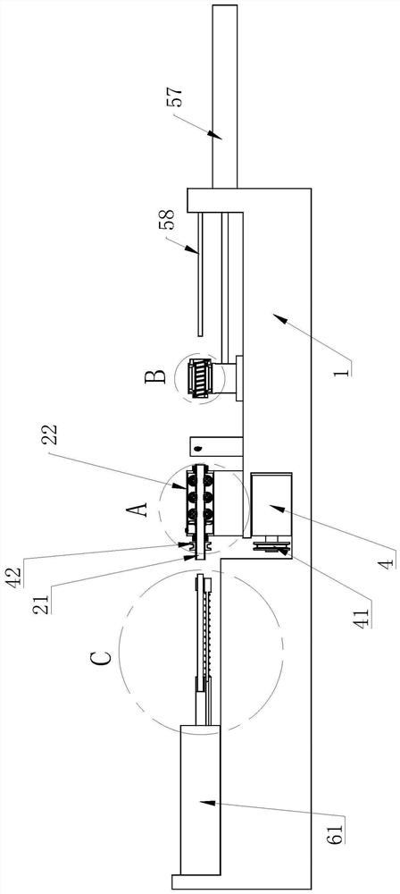
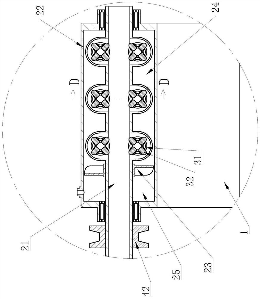
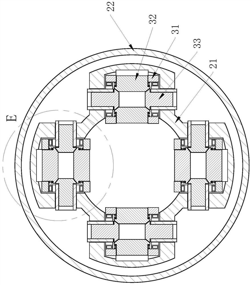
[0026] Such as figure 1 , figure 2 , image 3 with Image 6 As shown, the automatic feeding and discharging CNC lathe includes a main body 1, several workpiece clamping mechanisms, a feeding mechanism and a material discharging mechanism. The clamping assembly located on the main shaft 21, the clamping assembly includes a running wheel 31 rotatably connected to the main shaft 21, several clamping blocks 32 evenly distributed in the circumferential direction on the running wheel 31 and two plunger rods 33, two columns The stopper rod 33 is on the same straight line, the plunger rod 33 is perpendicular to the main shaft 21, each clamping block 32 is in the same plane, and the runner 31 is provided with a guide hole corre...


PUM


Abstract

The invention provides a self-adaptive clamping mechanism of a numerically controlled lathe, and belongs to the technical field of machine tools. The mechanism comprises a machine body and a plurality of workpiece clamping mechanisms, each workpiece clamping mechanism comprises a hollow main shaft, a cylinder body rotationally connected to the outside of the main shaft and a plurality of clamping assemblies located on the main shaft, each clamping assembly comprises a rotating wheel rotationally connected to the main shaft, a plurality of clamping blocks evenly distributed on the rotating wheel in the circumferential direction and two plunger rods, and the plunger rods are perpendicular to the main shafts; and the clamping blocks are located in the same plane, guide holes corresponding to the clamping blocks in a one-to-one manner are formed in the rotating wheels, the guide holes are perpendicular to the plunger rods, a hydraulic cavity is formed between each main shaft and the corresponding cylinder body, and each hydraulic cavity is connected with the liquid outlet end of a hydraulic pump. After the pressure of the hydraulic cavities is increased, the clamping blocks can protrude out of the wheel faces of the rotating wheels by driving the inner ends of the plunger rods to extrude the inner ends of the clamping blocks, the rotating wheels partially extend into the hollow cavities of the main shafts, and the cylinder bodies are fixedly connected with the machine body. The mechanism has the advantages that feeding and clamping can be achieved through the main shafts, and the like.

Description

technical field [0001] The invention belongs to the technical field of machine tools and relates to an adaptive clamping mechanism of a numerically controlled lathe. Background technique [0002] In the process of machining by CNC lathe, the disassembly and assembly efficiency of the workpiece has a great impact on the processing efficiency. The automation of feeding and discharging materials also depends heavily on the design of the tooling. There are high requirements for smoothness, and the realization of automatic material feeding and discharging can not only improve processing efficiency, but also have a positive effect on operation safety. [0003] The Chinese patent with the application number CN202010762778.1 discloses a spindle-loading CNC machine tool, which uses a cylinder and a one-way limit structure to realize the movement and clamping of the workpiece. It is not difficult to see that its clamping accuracy is low, and The main shaft cannot rotate, and can only...

Claims


Application Information

Patent Timeline
Patent Type & Authority Applications(China)
IPC IPC(8): B23B25/00B23Q3/00
CPCB23B25/00B23Q3/00
Inventor 朱彬陈佳
Owner 浙江迈兴途智能装备股份有限公司
Why Eureka
Try Eureka