Robot automatic welding control method and device, electronic equipment and storage medium

An automatic welding and control method technology, which is applied in the fields of devices, robot automatic welding control methods, electronic equipment and storage media, and can solve problems such as low compliance, high product defect rate, and unsatisfactory tensile strength of welded parts. , to achieve the effect of reducing the defect rate

Active Publication Date: 2021-11-09
JIHUA LAB
View PDF7 Cites 2 Cited by
  • Summary
  • Abstract
  • Description
  • Claims
  • Application Information

AI Technical Summary

Problems solved by technology

[0003] At present, when predicting the tensile strength of the welded part, it is usually to input the set welding parameters into the pre-set prediction model to obtain the predicted value of the tensile strength. However, the general prediction model regards the tensile strength as a static However, in practical applications, affected by noise, parameter uncertainty, etc., the automatic welding process of robots is a random process, and the final tensile strength is also a random quantity with certain probability characteristics. Therefore, the tensile strength The method of treating the strength as a static quantity to obtain the predicted value of the tensile strength has a low degree of conformity with the objective law, and it is easy to happen that the set welding parameters are judged to be reasonable but the final tensile strength of the welded part of the weldment does not meet the requirements situation, resulting in a high rate of defective products

Method used


Image

  • Robot automatic welding control method and device, electronic equipment and storage medium
  • Robot automatic welding control method and device, electronic equipment and storage medium
  • Robot automatic welding control method and device, electronic equipment and storage medium

Examples


Embodiment Construction

[0041] The following will clearly and completely describe the technical solutions in the embodiments of the present application with reference to the accompanying drawings in the embodiments of the present application. Obviously, the described embodiments are only some of the embodiments of the present application, not all of them. The components of the embodiments of the application generally described and illustrated in the figures herein may be arranged and designed in a variety of different configurations. Accordingly, the following detailed description of the embodiments of the application provided in the accompanying drawings is not intended to limit the scope of the claimed application, but merely represents selected embodiments of the application. Based on the embodiments of the present application, all other embodiments obtained by those skilled in the art without making creative efforts belong to the scope of protection of the present application.

[0042] It should ...


PUM


Abstract

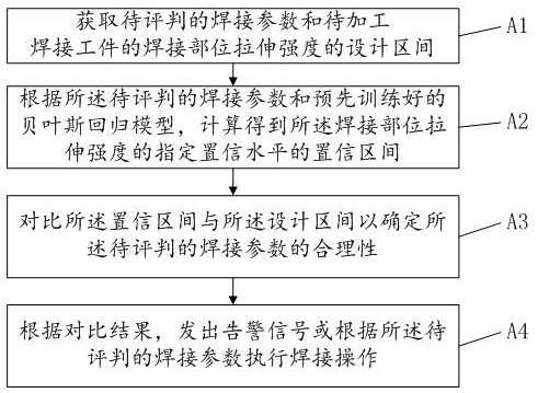
The invention belongs to the technical field of welding, and discloses a robot automatic welding control method and device, electronic equipment and a storage medium. The method comprises the steps that welding parameters to be judged and the design interval of the tensile strength of a welding part of a welding workpiece to be machined are obtained; according to the welding parameters to be judged and a Bayesian regression model trained in advance, the confidence interval of the specified confidence level of the tensile strength of the welding part is obtained through calculation; the confidence interval and the design interval are compared to determine the reasonability of the welding parameters to be judged; and an alarm signal is sent out according to the comparison result, or welding operation is executed according to the welding parameters to be judged. Due to the fact that the tensile strength is a random quantity, the situation that the reasonability of the welding parameters is judged through the confidence interval better conforms to an objective rule, the influence of various errors and noise is fully considered, the reasonability of the welding parameters can be judged more reasonably, and the reject ratio of welded products can be reduced advantageously.

Description

technical field [0001] The present application relates to the field of welding technology, in particular, to a robot automatic welding control method, device, electronic equipment and storage medium. Background technique [0002] Due to its high efficiency and strong adaptability to harsh environments, robot automatic welding is widely used in the field of batch processing and manufacturing of mechanical parts. Among them, the tensile strength of the welding part is an important indicator to measure the quality of the welding, and the tensile strength of the welding part is mainly affected by the welding parameters of the welding robot. The welding parameters include process parameters (such as: current / voltage, waiting time, number of welds) and tool parameters (such as: tool rotation speed, welding speed, axial force). Before welding a batch of workpieces, the tensile strength of the welded part is generally predicted according to the set welding parameters. When the pred...

Claims


Application Information

Patent Timeline
Patent Type & Authority Applications(China)
IPC IPC(8): B23K31/02B23K37/00B23K37/02B23K9/095B25J9/16
CPCB23K31/02B23K37/00B23K37/0252B23K9/0953B25J9/1607B25J9/161B25J9/1669
Inventor 范黎李一娴康信勇许泳
Owner JIHUA LAB
Why Eureka
Try Eureka