Ultrathin Nano-DLC coating for mobile phone camera mold

A mobile phone camera and mold technology, which is applied in the coating, metal material coating process, ion implantation plating, etc., can solve the problems of precision optical mold dimensional accuracy, affecting the mirror degree of camera mold, etc., to improve the production yield rate, Increase the service life and solve the effect of sticking mold

Inactive Publication Date: 2021-11-09
博赛纳涂层科技(苏州)有限公司
View PDF0 Cites 0 Cited by
  • Summary
  • Abstract
  • Description
  • Claims
  • Application Information

AI Technical Summary

Problems solved by technology

[0006] The invention provides an ultra-thin Nano-DLC coating for mobile phone camera molds, which solves the problem that ordinary DLC coatings not only have a great impact on the dimensional accuracy of precision optical molds, but also affect the mirror surface of camera molds

Method used


Image

  • Ultrathin Nano-DLC coating for mobile phone camera mold
  • Ultrathin Nano-DLC coating for mobile phone camera mold
  • Ultrathin Nano-DLC coating for mobile phone camera mold

Examples


no. 1 example

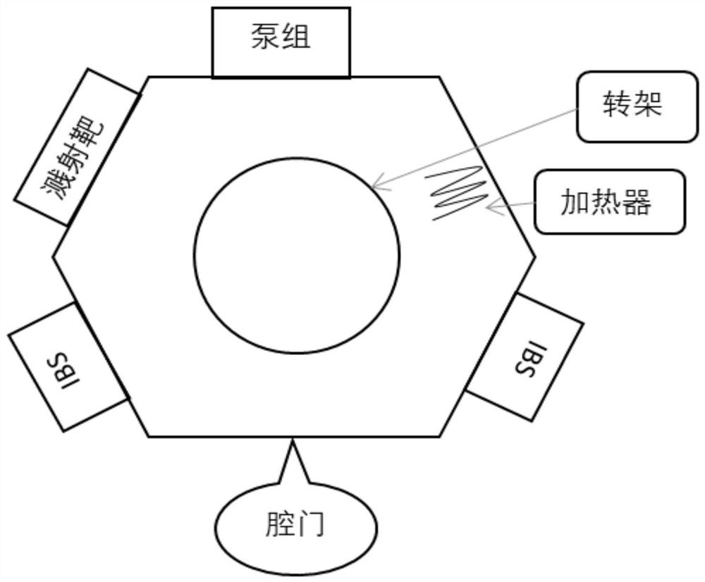
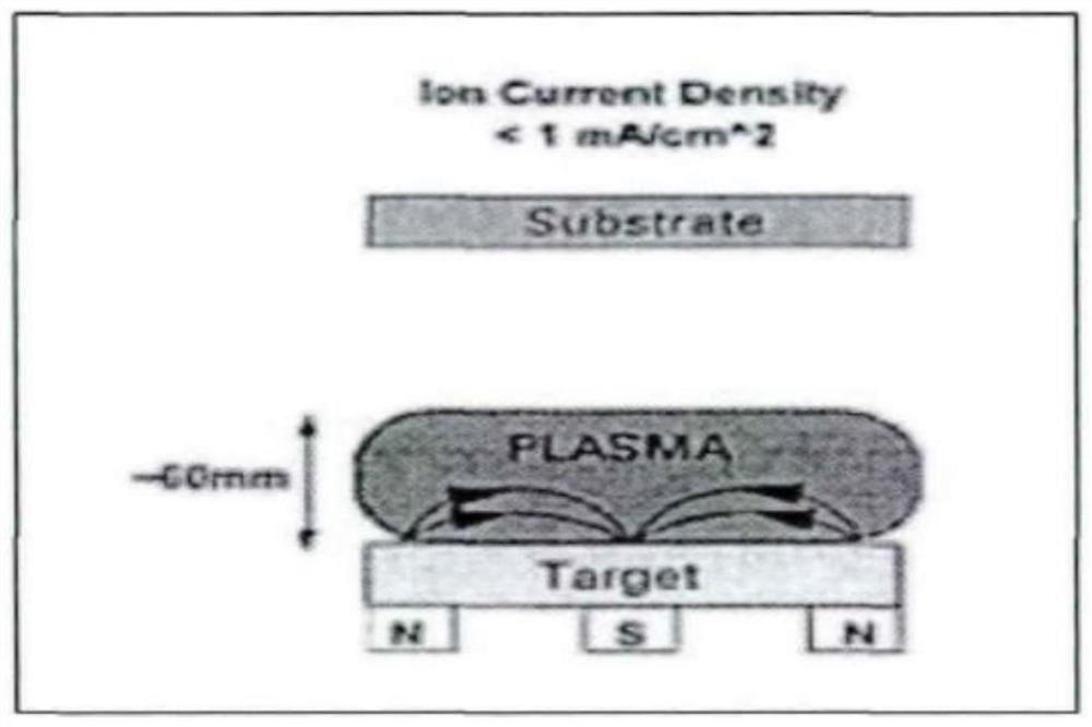
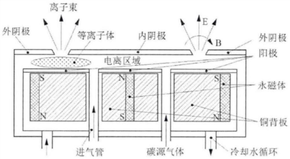
[0042] Please refer to figure 1 , figure 2 and image 3 , figure 1 The cavity process flow diagram of the first embodiment of the ultra-thin Nano-DLC coating for the mobile phone camera mold provided by the present invention; figure 2 It is a schematic diagram of magnetron sputtering deposition of the present invention; image 3 It is a schematic diagram of the ion beam structure of the anode layer of the present invention. Ultra-thin Nano-DLC coating for mobile phone camera molds, made by the following methods:

[0043] S1. Open the chamber door, clamp the cleaned products to the turntable, and close the chamber door after confirming that the turntable is smooth and free of jamming;

[0044] S2. Find the pump set corresponding to the pumping on the software interface, and vacuum the cavity according to the pumping standard;

[0045] S3. When the cavity is pumped to 5.0E-3Pa, set the heater temperature and turn on the heater to start heating;

[0046] S4. After waitin...

no. 2 example

[0068] Please refer to Figure 4 and Figure 5 , based on the ultra-thin Nano-DLC coating for mobile phone camera molds provided in the first embodiment of the application, the second embodiment of the application proposes another ultra-thin Nano-DLC coating based on mobile phone camera molds DLC coating. The second embodiment is only a preferred mode of the first embodiment, and the implementation of the second embodiment will not affect the independent implementation of the first embodiment.

[0069] Specifically, the difference based on the ultra-thin Nano-DLC coating used for the mobile phone camera mold provided by the second embodiment of the application is that based on the ultra-thin Nano-DLC coating used for the mobile phone camera mold is also included in the The detection device 1 used for visual inspection of products, the detection device 1 includes a support frame 11, the top of the support frame 11 is fixedly connected with a mounting horizontal plate 12, and ...


PUM

PropertyMeasurementUnit
thicknessaaaaaaaaaa

Abstract

The invention provides an ultrathin Nano-DLC coating for a mobile phone camera mold. The ultrathin Nano-DLC coating for the mobile phone camera mold is prepared by adopting the following method of S1, opening a cavity door, clamping a cleaned product onto a rotating stand, and closing the cavity door after the rotating stand is smooth and not blocked; S2, finding a pump set corresponding to air exhaust on a software interface, and vacuumizing a cavity according to an air exhaust standard; S3, when the cavity is pumped to 5.0 E-3 Pa, setting the temperature of a heater, starting the heater, and starting heating; and S4, after the temperature is increased to the set temperature, heat preservation for 10-30 min, and continuing to vacuumize till the vacuum degree needed by the technology is reached. According to the ultrathin Nano-DLC coating for the mobile phone camera mold, the surface of a product is plated with the thin Nano-DLC coating, so that the surface of the mold is harder, the service life of the mold is prolonged, the bad problems of mold sticking and the like are solved, the production yield is increased, and the size precision of the mold is basically not affected.

Description

technical field [0001] The invention relates to the field of ultra-thin Nano-DLC coatings for mobile phone camera dies, in particular to an ultra-thin Nano-DLC coating for mobile phone camera dies. Background technique [0002] At present, the popularization of mobile phones is getting higher and higher, and the related industries of mobile phones are also developing vigorously, and the mobile phone camera business is undoubtedly a very important link in the mobile phone industry chain. [0003] In the automatic production process of the mobile phone camera, the use of the camera mold is inseparable. The camera shell can be quickly formed through the camera mold, which is convenient for the rapid assembly of the camera and the mobile phone. However, the mobile phone camera mold has a low surface hardness of the camera mold and a long service life. Shorter length, serious camera mold sticking problem, low yield rate, high cost and other issues. [0004] In the prior art, in ...

Claims


Application Information

Patent Timeline
Patent Type & Authority Applications(China)
IPC IPC(8): C23C14/35C23C14/06C23C14/02B82Y40/00B29C33/72
CPCC23C14/35C23C14/0605C23C14/022B82Y40/00B29C33/72
Inventor 赵红艳徐少宁李吉庆刘胡山
Owner 博赛纳涂层科技(苏州)有限公司
Why Eureka
Try Eureka