Construction method for stopping underground water of building foundation pit

A groundwater and foundation pit technology, applied in construction, infrastructure engineering, excavation, etc., can solve problems such as hidden safety hazards, poor lap joints, water leakage, etc., and achieve significant water stop effects and cost savings.

Inactive Publication Date: 2021-11-09
BEIJING VIBROFLOTATION ENG
View PDF4 Cites 0 Cited by
  • Summary
  • Abstract
  • Description
  • Claims
  • Application Information

AI Technical Summary

Problems solved by technology

[0006] 1. High cost
Since Beijing has started to collect water resource treatment fees, the price is 4.3 yuan / ton, and the water in the foundation pit of the building is basically drained, and the amount of water pumped is very large. It is initially estimated that the project will need to pay at least 100 million yuan to the taxation department of Fengtai District. Resource fee, the cost is too high
[0007] 2. At present, the Beijing Municipal Government does not advocate this method
[0008] 3. The traditional pumping method will pump the sand particles filled in the pebbles to the surface together with water, causing the pebble layer to sink! Since the shortest distance between this project and the built civil buildings is only 3.9m, it is easy to cause cracks in nearby buildings, posing safety hazards!
[0009] 4. It is impossible to fundamentally solve the problem of groundwater pouring into the building foundation pit by only using the method of pumping water without taking other measures
[0010] 5. Large-grained pebbles are piled up inside the building foundation pit to form a water-stop wall. The disadvantage is that its verticality cannot be guaranteed, and there are still problems of loose lap joints and water leakage!
[0011] In addition, after many rounds of expert demonstrations, they are not fully sure about this special situation, and there are many failure cases nearby.

Method used


Image

  • Construction method for stopping underground water of building foundation pit
  • Construction method for stopping underground water of building foundation pit
  • Construction method for stopping underground water of building foundation pit

Examples


Embodiment Construction

[0082] The technical solutions and features of the present invention will be described in detail below in conjunction with the accompanying drawings and embodiments. It should be noted that various modifications can be made to the embodiments disclosed herein, therefore, the embodiments disclosed in the specification should not be regarded as limitations on the present invention, but only as examples of embodiments, and its purpose is to make the present invention The features of the invention are self-evident.

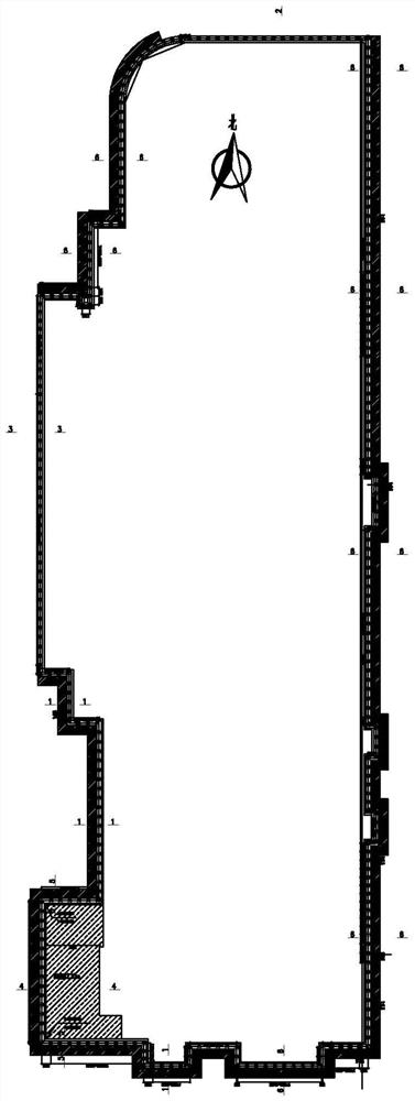
[0083] When digging a building foundation pit, as the depth of the building foundation pit increases, it is necessary to pour a circle of support piles around the building foundation pit, and then pour crown beams on the top of the support piles, and through the crown beams, each support pile Connect them together, and finally, fix several anchor cables and anchor rods between the surroundings of the foundation pit and the support piles / crown beams for further reinfor...


PUM


Abstract

The invention provides a construction method for stopping underground water of a building foundation pit. According to the construction method, a circle of water stop curtains are formed on the outer sides of support piles of the building foundation pit through a novel three-pipe method high-pressure jet grouting construction process; a circle of secant piles are formed on the inner sides of the support piles; a circle of dam foundation sand gravel curtains are formed between the support piles and the secant piles through a grouting construction process; and the water stop purpose is achieved through the combined action of the water stop curtains on the outer sides of the support piles, the secant piles on the inner sides of the support piles and the dam foundation sand gravel curtains. The method effectively solves the problem that the underground water flows into the building foundation pit, and is recognized by experts in the industry. Compared with a traditional precipitation method, the method has the advantages that the problem that the underground water flows into the building foundation pit is fundamentally prevented, the water stop effect is remarkable, the manufacturing cost is saved, the surrounding underground water level is not influenced, and the influence of the surrounding underground water level is avoided.

Description

technical field [0001] The invention relates to a method for preventing groundwater from pouring into a building foundation pit. The invention belongs to the technical field of building construction. Background technique [0002] As we all know, before the construction of high-rise buildings, it is necessary to dig down figure 1 The building foundation pit shown is to reinforce the building foundation pit, that is, laying a foundation is often said by those skilled in the art. After the foundation is strengthened, the building is built on the foundation. The higher the building on the ground, the deeper the building foundation pit dug under it. Usually, before excavating building foundation pits, surveyors will measure the groundwater level in the area, with the purpose of making the excavated building foundation pits above the groundwater level. [0003] However, due to various reasons, after the depth of the building foundation pit is determined and the building foundat...

Claims


Application Information

Patent Timeline
Patent Type & Authority Applications(China)
IPC IPC(8): E02D5/18E02D31/02E02D17/02E02D17/04E02D15/00
CPCE02D5/18E02D31/02E02D17/02E02D17/04E02D15/00
Inventor 潘永玉徐海荣张四元秦晓东杨继明赵远利晁李军袁鑫
Owner BEIJING VIBROFLOTATION ENG
Why Eureka
Try Eureka