Bipolar longitudinal magnetic contact structure and vacuum arc-extinguishing chamber
A vacuum interrupter and longitudinal magnet technology, applied in high-voltage air circuit breakers, electrical components, electrical switches, etc., can solve problems such as arc concentration, and achieve reliable connection, compact structure, and good reliability.
- Summary
- Abstract
- Description
- Claims
- Application Information
AI Technical Summary
Problems solved by technology
Method used
Image
Examples
Embodiment 1
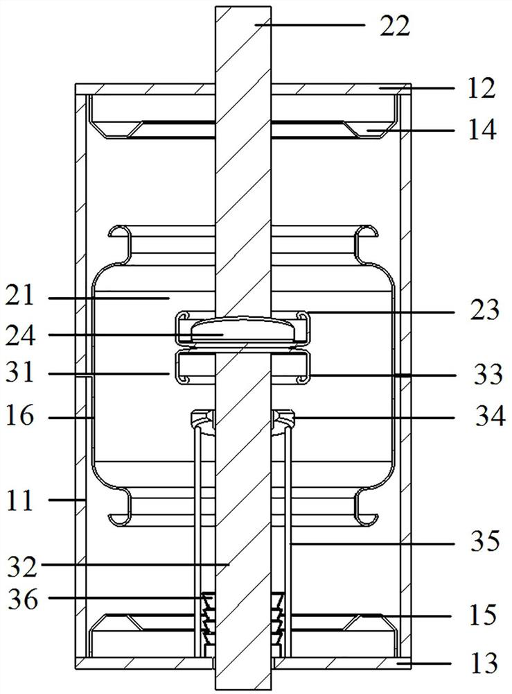
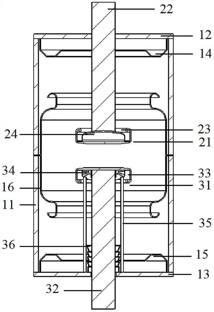
[0065] Such as figure 1 and figure 2 As shown, the vacuum interrupter includes an arc-extinguishing chamber shell 11, the arc-extinguishing chamber shell 11 adopts a porcelain shell, and its axial ends are respectively welded and fixed to the static side cover plate 12 and the moving side cover plate 13, and the arc-extinguishing chamber shell 11 A contact assembly is arranged inside, and the contact assembly adopts a bipolar longitudinal magnetic contact structure.
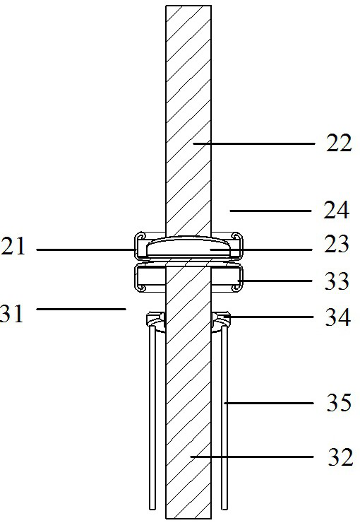
[0066] The bipolar longitudinal magnetic contact structure includes a static contact assembly 21 and a moving contact assembly 31 . The static contact assembly 21 includes a static conductive rod 22 , a static contact piece 23 , and a U-shaped iron core 24 on the static side; The longitudinal sections of the static contact piece 23 and the moving contact piece 33 are both U-shaped, and the U-shaped openings of the two are facing oppositely. The back of the radial center of the static contact piece 23 is welde...
Embodiment 2
[0073] The difference between this embodiment and Embodiment 1 is that in Embodiment 1, the moving-side iron core support 35 is a support rod, while in this embodiment, the moving-side iron core support 35 is a support cylinder, and the support cylinder is fixed on Inside the moving side cover plate 13, the moving conducting rod 32 passes through the supporting cylinder. In other embodiments, the moving-side iron core support member 35 may also be in other forms, such as a frame form; in addition, in other embodiments, the number of support rods may be only one, or more than three.
Embodiment 3
[0075] The difference between this embodiment and Embodiment 1 is that in Embodiment 1, the support rod is welded and fixed on the movable side cover plate 13, while in this embodiment, the end of the support rod is provided with a flange structure, and the The structural assembly is fixed on the moving end cover.
PUM
 Abstract
Description
Claims
Application Information
 - R&D
- Intellectual Property
- Life Sciences
- Materials
- Tech Scout
- Unparalleled Data Quality
- Higher Quality Content
- 60% Fewer Hallucinations
Browse by: Latest US Patents, China's latest patents, Technical Efficacy Thesaurus, Application Domain, Technology Topic, Popular Technical Reports.
© 2025 PatSnap. All rights reserved.Legal|Privacy policy|Modern Slavery Act Transparency Statement|Sitemap|About US| Contact US: help@patsnap.com


