
Rail-to-rail output circuit of high-speed fully differential amplifier and high-speed fully differential amplifier

A fully differential amplifier and output circuit technology, applied in the direction of differential amplifiers, amplifiers, push-pull amplifiers, etc., can solve the problems of negative slew rate limitation, increased circuit complexity and design difficulty, complex quiescent current control structure, etc. Achieve the effect of high-speed amplified rail-to-rail output

Pending Publication Date: 2021-11-09
NO 24 RES INST OF CETC
View PDF0 Cites 2 Cited by
  • Summary
  • Abstract
  • Description
  • Claims
  • Application Information

AI Technical Summary

Problems solved by technology

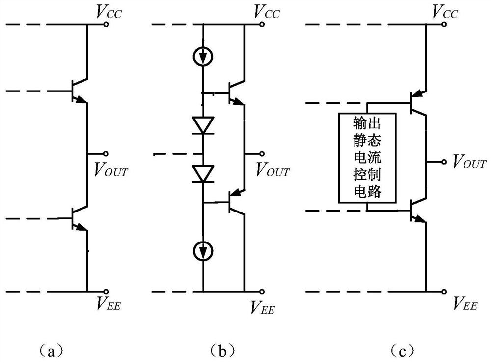
[0004] ①, such as figure 1 In the NPN emitter follower output stage shown in (a), the positive saturation voltage drop of this output structure is much larger than the negative phase saturation voltage drop, and the negative slew rate is severely limited, so it is impossible to achieve rail-to-rail output and large slew rate;
[0005] ②, such as figure 1 The NPN and PNP complementary follower outputs shown in (b), the output swing of this output structure has a saturation voltage drop of VBE+VCESAT from the positive and negative power supply voltages, and it is also impossible to achieve rail-to-rail output;
[0006] ③, such as figure 1 The NPN and PNP complementary common emitter push-pull output shown in (c), although this output structure can achieve rail-to-rail output, it requires a complex quiescent current control structure, which greatly increases the complexity of the circuit and the difficulty of design

Method used


Image

  • Rail-to-rail output circuit of high-speed fully differential amplifier and high-speed fully differential amplifier
  • Rail-to-rail output circuit of high-speed fully differential amplifier and high-speed fully differential amplifier
  • Rail-to-rail output circuit of high-speed fully differential amplifier and high-speed fully differential amplifier

Examples


Embodiment Construction

[0026] Embodiments of the present invention are described below through specific examples, and those skilled in the art can easily understand other advantages and effects of the present invention from the content disclosed in this specification. The present invention can also be implemented or applied through other different specific implementation modes, and various modifications or changes can be made to the details in this specification based on different viewpoints and applications without departing from the spirit of the present invention.

[0027] see Figure 2 to Figure 3 . It should be noted that the diagrams provided in this embodiment are only schematically illustrating the basic idea of ​​the present invention, so that only the components related to the present invention are shown in the diagrams rather than the number, shape and Dimensional drawing, the type, quantity and proportion of each component can be changed arbitrarily during actual implementation, and the...


PUM


Abstract

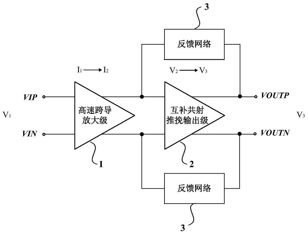
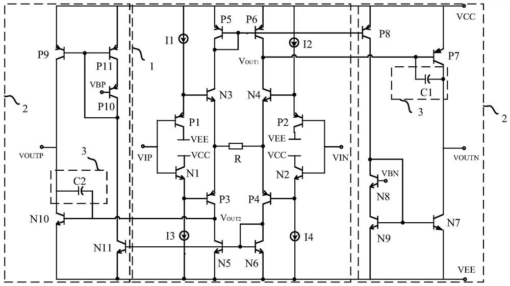
The invention provides a rail-to-rail output circuit of a high-speed fully-differential amplifier and the high-speed fully-differential amplifier. The structural design of a high-speed transconductance amplification stage and a novel complementary common-emitter push-pull output stage is combined; therefore, high-speed transconductance amplification and buffering can be carried out on a differential signal output by a pre-stage of the amplifier, and rail-to-rail output close to a positive / negative power supply is realized; through a feedback network arranged between the output end and the input end, the frequency roll-off can be effectively compensated, and the output stability is improved; the rail-to-rail output circuit is realized based on a complementary bipolar process and an all-longitudinal transistor, and high-speed amplification and rail-to-rail output are realized while a high-speed operational amplifier is ensured to be applied by reducing power supply voltage, so the signal-to-noise ratio and the speed / bandwidth index of the rail-to-rail output circuit are not influenced.

Description

technical field [0001] The invention relates to the technical field of semiconductor integrated circuit design, in particular to a rail-to-rail output circuit of a high-speed full differential amplifier and a high-speed full differential amplifier. Background technique [0002] Amplifiers are an integral part of most circuits, and their performance largely determines the performance of the entire circuit or even the system. With the popularization of battery-powered portable devices, working under low-voltage and low-power consumption conditions has gradually become an essential requirement for the system. The most immediate effect of lowering the supply voltage is a reduction in the output signal amplitude, which results in a significant reduction in the signal-to-noise ratio. Compared with single-ended output amplifiers, the differential output amplitude of fully differential output amplifiers can be doubled, which can greatly improve the signal-to-noise ratio of the syst...

Claims


Application Information

Patent Timeline
IPC IPC(8): H03F3/45H03F1/34H03F3/26
CPCH03F3/4508H03F1/34H03F3/26Y02D30/70
Inventor 范国亮何峥嵘王成鹤杨阳周远杰
Owner NO 24 RES INST OF CETC
Learn More