A waste rubber tire pyrolysis recycling equipment

A waste rubber and recycling equipment technology, applied in plastic recycling, mechanical material recycling, recycling technology and other directions, can solve the problems of reducing tire cracking speed, no wire cleaning, affecting rubber processing, etc., to speed up cracking speed and speed up filtration speed , the effect of accelerating the cracking efficiency

Active Publication Date: 2022-03-18
江苏绿源橡胶资源循环利用创新中心有限公司
View PDF8 Cites 1 Cited by
  • Summary
  • Abstract
  • Description
  • Claims
  • Application Information

AI Technical Summary

Problems solved by technology

[0003] At present, the treatment of waste rubber tires is to directly put the tires into the cracking cylinder for melting and cracking. Since the tires are not crushed before placing them, the tires are kept in close contact, which in turn reduces the cracking speed of the tires. , and after the cracking of the tire, a certain amount of steel wire remains in the cracked rubber tire. At present, the steel wire is not well cleaned, which in turn affects the treatment of the cracked rubber

Method used


Image

  • A waste rubber tire pyrolysis recycling equipment
  • A waste rubber tire pyrolysis recycling equipment
  • A waste rubber tire pyrolysis recycling equipment

Examples


Embodiment 1

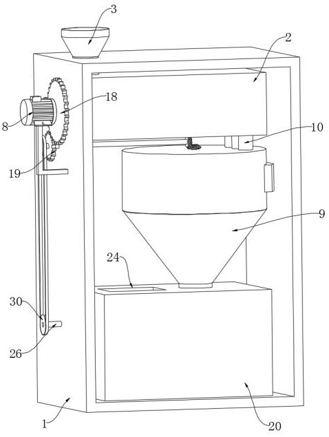
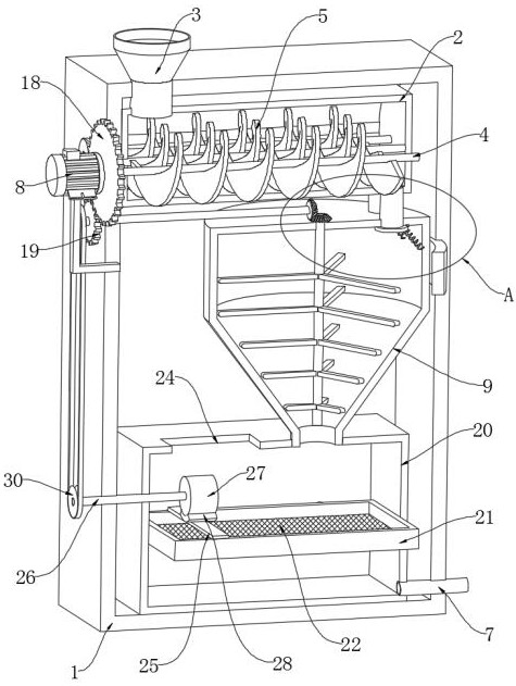
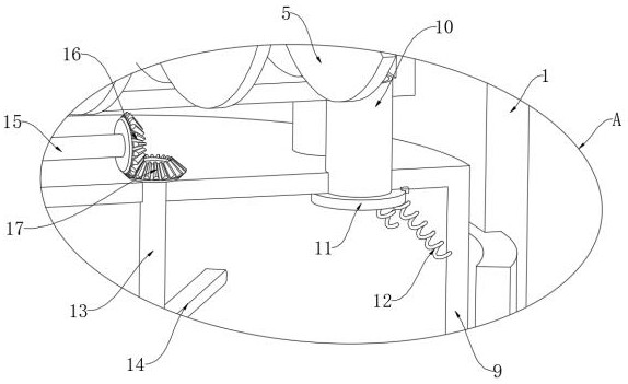
[0030] refer to Figure 1-Figure 6 , a waste rubber tire cracking recovery equipment, including a shell 1, the shell 1 is provided with a crushing mechanism for crushing the tires, the crushing mechanism includes a crushing box 2 fixedly connected above the inner wall of the shell 1, and the crushing mechanism The top of the crushing box 2 is fixedly connected with the feeding pipe 3, the inner wall of the crushing box 2 is rotatably connected with a plurality of rotating shafts 4, and the side walls of the plurality of rotating shafts 4 are fixedly connected with spiral crushing leaves 5, and the gap between two adjacent spiral crushing leaves 5 Arranged in a staggered manner, one end of a plurality of rotating shafts 4 runs through the crushing box 2 and the side wall of the housing 1 respectively and is fixedly connected with a plurality of synchronous wheels 6, which are connected by a synchronous belt, and the side wall of the housing 1 is fixed by a bracket A motor 8 is ...

Embodiment 2

[0044] refer to Figure 7-Figure 8 , different from Embodiment 1, the crushing box 2 is provided with a cleaning mechanism for cleaning rubber, the cleaning mechanism includes a hollow plate 31 fixedly embedded in the top of the crushing box 2, and a plurality of water outlets are provided at the bottom of the hollow plate 31. The hole 32, the side wall of the housing 1 is fixedly connected with two sliding plugs 33, the inner walls of the two sliding plugs 33 are both sealed and slidably connected with a sliding plug 34, and the inner walls of the two sliding plugs 33 are fixedly connected with a one-way water suction pipe 35 , the inner walls of the two sliding plug cylinders 33 are connected with the inner wall of the hollow plate 31 through the one-way outlet pipe 36, the side wall of the housing 1 is provided with a through groove 37, the inner wall of the through groove 37 is slidingly connected with a slide plate 38, and the side wall of the slide plate 38 is passed thro...

Embodiment 3

[0048] refer to Figure 9 , different from Embodiment 1, the side wall of the stirring rod 14 is provided with a chute 41, the inner wall of the chute 41 is slidably connected with a slide bar 42, and the end of the slide bar 42 away from the chute 41 is fixedly connected with a scraper 43, and the scraper 43 The side wall is attached to the inner wall of the cracking cylinder 9 , and the end of the sliding rod 42 away from the scraper 43 is elastically connected to the inner wall of the chute 41 through the second spring 44 .

[0049] In the present embodiment, when a plurality of stirring rods 14 are rotated to stir the tire, at this time, under the action of the second spring 44, the slide bar 42 drives the scraper 43 to be attached to the inner wall of the cracking cylinder 9 all the time, and then the cracking cylinder can be Scrape off the rubber with viscosity on the inner wall of the cracking tube 9 to avoid more rubber sticking to the inner wall of the cracking tube 9...


PUM


Abstract

The invention discloses a cracking and recycling equipment for waste rubber tires, which comprises a casing, a crushing mechanism for crushing tires is arranged in the casing, and the crushing mechanism includes a crushing box fixedly connected above the inner wall of the casing , the top of the crushing box is fixedly connected with a feeding pipe, the inner wall of the crushing box is rotatably connected with a plurality of rotating shafts, and the side walls of the plurality of rotating shafts are fixedly connected with spiral crushing leaves, and between two adjacent spiral crushing leaves One end of the plurality of rotating shafts runs through the crushing box and the side wall of the housing respectively and is fixedly connected with a plurality of synchronous wheels, which are connected by a synchronous belt, and the side wall of the housing is connected by a bracket A motor is fixedly connected, and the movable end of the motor is fixedly connected with one end of one of the rotating shafts. In the present invention, by setting a crushing mechanism, the rotation of a plurality of spiral crushing leaves can not only transport the tires, but also crush the tires, thereby accelerating the cracking speed of the tires.

Description

technical field [0001] The invention relates to the technical field of rubber tire recycling, in particular to a cracking and recycling equipment for waste rubber tires. Background technique [0002] Pyrolysis of waste rubber tires is one of the effective methods to deal with waste rubber tires. Pyrolysis treatment has no pollutant discharge, and can also recover fuel oil and carbon black, which is beneficial to environmental protection and resource utilization, and has high economic value. [0003] At present, the treatment of waste rubber tires is to directly put the tires into the cracking cylinder for melting and cracking. Since the tires are not crushed before placing them, the tires are kept in close contact, which in turn reduces the cracking speed of the tires. , and after the tire is cracked, a certain amount of steel wire remains in the cracked rubber tire. At present, the steel wire is not cleaned well, which affects the treatment of the cracked rubber. Contents...

Claims


Application Information

Patent Timeline
Patent Type & Authority Patents(China)
IPC IPC(8): B29B17/04B29B17/02
CPCB29B17/04B29B17/02B29B2017/0476B29B2017/0496B29B2017/0224Y02W30/62Y02W30/52
Inventor 吴三丫
Owner 江苏绿源橡胶资源循环利用创新中心有限公司
Why Eureka
Try Eureka