Semi-automatic electrical testing machine testing equipment

A technology for testing equipment and electrical measuring machines, which is applied to parts of electrical measuring instruments, measuring electricity, measuring devices, etc., can solve the problems affecting the accuracy of test results, low work efficiency, and errors in test results, and achieves simple structure, Improve work efficiency and improve accuracy

Pending Publication Date: 2021-11-12
深圳市合力泰光电有限公司
View PDF0 Cites 0 Cited by
  • Summary
  • Abstract
  • Description
  • Claims
  • Application Information

AI Technical Summary

Problems solved by technology

[0004] The purpose of the present invention is to provide a semi-automatic electric measuring machine testing equipment, aiming at solving the problem that the existing electric measuring machine testing equipment has long test time, low work efficiency, and often errors in test results, thus affecting the accuracy of test results question

Method used


Image

  • Semi-automatic electrical testing machine testing equipment
  • Semi-automatic electrical testing machine testing equipment

Examples


Embodiment 1

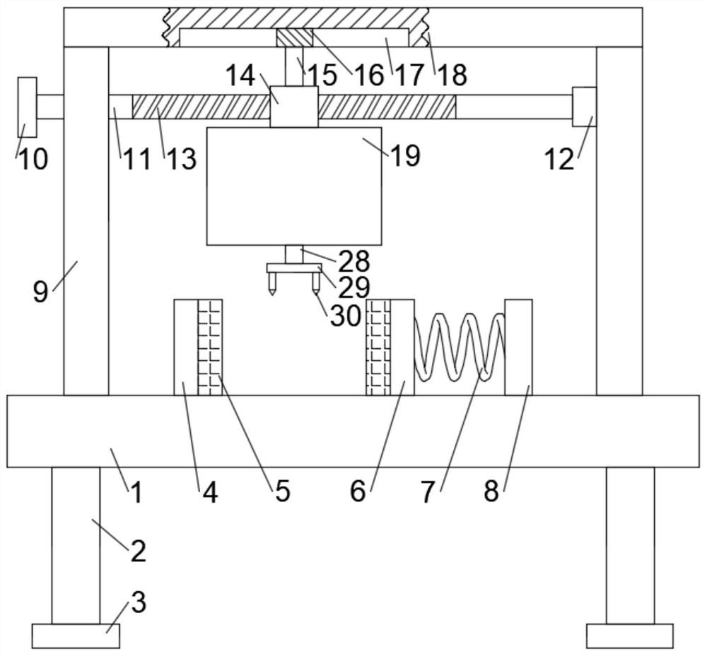
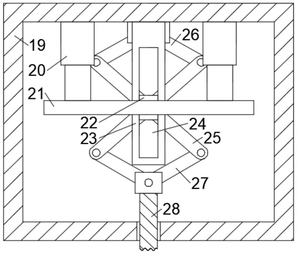
[0018] see Figure 1-2 , in an embodiment of the present invention, a semi-automatic electric measuring machine testing equipment, including a test platform 1, the limit block 4 is fixedly connected to the surface of the test platform 1 on one side, and the surface of the other side of the test platform 1 is fixedly connected to There is a fixed block 8, the side wall of the fixed block 8 and the limit block 4 are fixedly connected with a spring 7, and the other end of the spring 7 is fixedly connected with a moving block 6, and the two sides of the test platform 1 are fixedly connected with spacers. plate 9, the partition plate 9 is connected with a sliding assembly, the sliding assembly is connected with a box body 19, and a lifting assembly is connected inside the box body 19, and the lifting assembly is connected with a movable rod 28, and the movable rod 28 runs through The inner wall of the box body 19 extends to the bottom of the box body 19 , and the end is connected w...

Embodiment 2

[0021] see figure 1 , in an embodiment of the present invention, the four corners of the bottom surface of the test platform 1 are fixedly connected with fixed legs 2 , and the bottom ends of the fixed legs 2 are connected with anti-skid pads 3 .

[0022] In the embodiment of the present invention, fixed legs 2 are provided to fix and support the test platform 1, and anti-slip pads 3 are provided to increase the contact area with the ground and increase the friction with the ground, making the equipment more reliable and stable.

Embodiment 3

[0024] see figure 1 , in an embodiment of the present invention, a buffer pad 5 is connected to the side walls of the limiting block 4 and the moving block 6 facing each other.

[0025] In the embodiment of the present invention, a buffer pad 5 is provided to play the role of buffering and shock absorption, and prevent the limit block 4 and the moving block 6 from causing damage to the surface of the product to be tested.


PUM


Abstract

The invention relates to the technical field of testing equipment, in particular to semi-automatic electrical testing machine testing equipment which comprises a testing platform, a limiting block is fixedly connected to the surface of one side of the testing platform, a fixing block is fixedly connected to the surface of the other side of the testing platform, and springs are fixedly connected to the side walls, in the same direction, of the fixing block and the limiting block. the other end of the spring is fixedly connected with a moving block, two sides of the test platform are fixedly connected with partition plates, the partition plates are connected with a sliding assembly, and the sliding assembly is connected with a box body. The semi-automatic electrical testing machine testing equipment solves the problems that the existing testing equipment of the electric testing machine is long in testing time, low in working efficiency, causes frequent errors of testing results, and thenthe accuracy of a test result is influenced. According to the invention, the semi-automatic electrical testing machine testing equipment is reasonable in structural design, is simple in structure, is convenient to use, achieves the automatic testing, improves the working efficiency, reduces the errors during the testing, improves the accuracy of the testing result, and is very good in practicality.

Description

technical field [0001] The invention relates to the technical field of testing equipment, in particular to a semi-automatic electric measuring machine testing equipment. Background technique [0002] Testing equipment, also known as testing equipment, refers to the general designation of all instruments, meters, devices, systems and their required devices, components, auxiliary equipment, etc. used for testing. There are many types of testing equipment, including measuring equipment calipers, balances, dotting machines, etc. In addition, quality testing and analysis equipment, material testing, packaging testing equipment, etc. are also common testing equipment. [0003] The electric measuring machine test equipment in the prior art usually uses a multimeter to test the product manually, but the test time is long, the work efficiency is low, and the test result often has errors, which affects the accuracy of the test result. Contents of the invention [0004] The purpose ...

Claims


Application Information

Patent Timeline
Patent Type & Authority Applications(China)
IPC IPC(8): G01R1/04G01R31/00
CPCG01R1/04G01R1/0425G01R31/00
Inventor 马承义
Owner 深圳市合力泰光电有限公司
Why Eureka
Try Eureka