Cable bent tower beam light-weight support design and construction method

A design method and lightweight technology, applied in design optimization/simulation, special data processing applications, instruments, etc., can solve problems such as unreasonable structural design of beam support, large design load, waste of resources, etc., and achieve a wide range of applications. , Improve safety and ensure the effect of design accuracy

Pending Publication Date: 2021-11-12
CHINA CONSTR SIXTH ENG DIV CORP +1
View PDF0 Cites 1 Cited by
  • Summary
  • Abstract
  • Description
  • Claims
  • Application Information

AI Technical Summary

Problems solved by technology

The traditional method fails to make full use of the "portal rigid frame", that is, the beam structure that is poured first and the two-leg tower columns form the self-carrying capacity of the portal structure, which leads to unreasonable design of the beam support structure, resulting in the failure of the support structure. The design load is much greater than the actual load, resulting in waste of resources

Method used


Image

  • Cable bent tower beam light-weight support design and construction method
  • Cable bent tower beam light-weight support design and construction method
  • Cable bent tower beam light-weight support design and construction method

Examples


Embodiment 1

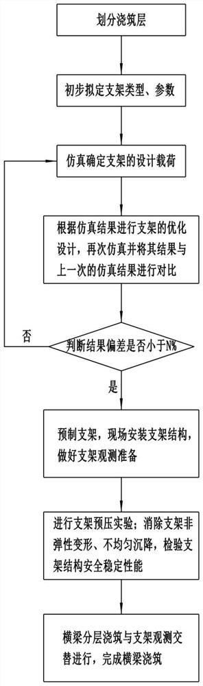
[0031] The specific steps of the design method of the present embodiment are:

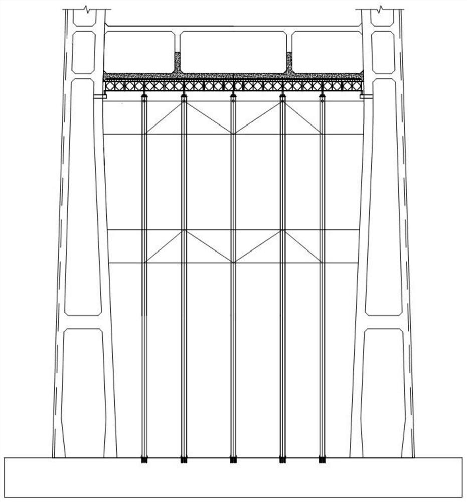
[0032] Step 1, dividing each pouring layer of the cable tower beam and determining the height of each pouring layer, the present embodiment divides the horizontal beam into two layers of equal height;

[0033] Step 2: Preliminarily draw up the structural form of the beam support, the type and parameters of the support section according to the division results of step 1; the tentative value Q=Q1+Q2*A% of the design load of the preliminary design of the beam support, where Qi is the i-th For the weight of concrete layered by layer, the proportion value A% is 60%; with Q as the tentative design load, the preliminary design of parameters such as the support structure form and support section type is carried out in combination with the spatial position and type of the beam. The preliminary design of this embodiment is floor-standing Steel pipe support;

[0034] Step 3, use the simulation software to si...

Embodiment 2

[0043] The specific steps of the design method of the present embodiment are:

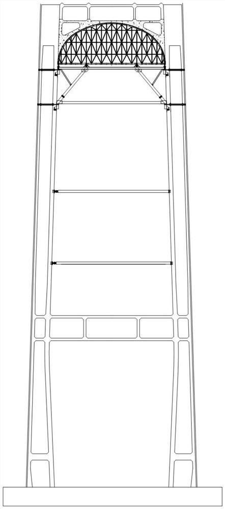
[0044] Step 1: Divide each pouring layer of the cable tower beam and determine the height of each pouring layer. In this embodiment, the arc-shaped beam is divided into four layers, and the first three layers of beams are closed after pouring is completed. Therefore, Q1 in the original equation should be The sum of the quality of the first three layers of concrete in the present embodiment;

[0045] Step 2: Preliminarily draw up the structural form of the beam support, the type and parameters of the support section according to the division results of step 1; the tentative value Q=(Q1+Q2+Q3)+Q4*A% of the design load of the preliminary design of the beam support , the proportional value A% is taken as 60%; with Q as the tentative design load, the preliminary design of parameters such as the support structure form and the support section type is carried out in combination with the spatial position an...


PUM


Abstract

The invention provides a cable bent tower beam light-weight support design and construction method. The method comprises the specific steps: dividing all pouring layers of a cable bent tower beam, and determining the height of each pouring layer; preliminarily drawing up the structural form of the cross beam support and the type and parameter of the support section; determining a support structure design load; re-determining the section type and parameters of the support, and comparing the section type and parameters with the preliminarily prepared result; repeating the previous two steps until the deviation of the front and back comparison of the load value borne by the support does not exceed the limit value N%; mounting a support structure on site, and making support observation preparation; carrying out a support pre-pressing experiment; and alternately carrying out cross beam layered pouring and support observation, and completing cross beam pouring. Compared with the traditional method, the method can reduce the material consumption of the cross beam bracket, and realizes cost reduction and benefit increase; a design mode of multi-time simulation and optimization is adopted, so that the design precision is ensured, and the safety is improved; and the method is suitable for various layered pouring construction, and the application range is very wide.

Description

technical field [0001] The invention relates to the technical field of bridge construction, in particular to a design and construction method of a light-weight support for a cable tower beam. Background technique [0002] The beams of the cable towers of long-span bridges are generally cast in layers. For the design and construction of the beam support, traditional methods use the dead weight of the entire beam plus live loads such as personnel and tools as the design load. The traditional method fails to make full use of the "portal rigid frame", that is, the beam structure that is poured first and the two-leg tower columns form the self-carrying capacity of the portal structure, which leads to unreasonable design of the beam support structure, resulting in the failure of the support structure. The design load is much larger than the actual load, resulting in a waste of resources. Contents of the invention [0003] The invention aims to solve the deficiencies of the pri...

Claims


Application Information

Patent Timeline
Patent Type & Authority Applications(China)
IPC IPC(8): G06F30/13G06F30/23G06F119/14
CPCG06F30/13G06F30/23G06F2119/14
Inventor 谢朋林高璞王殿永赵文磊黎人亮杨毅辉耿文宾陈诗祥李明刘传东周俊龙强伟亮赵云雷张敏月
Owner CHINA CONSTR SIXTH ENG DIV CORP
Why Eureka
Try Eureka