Refrigeration cycle device

A refrigeration cycle, refrigerant technology, applied in the direction of refrigerators, refrigeration and liquefaction, irreversible cycle compressors, etc., can solve problems affecting compressor durability and so on

Active Publication Date: 2021-11-12
DENSO CORP
View PDF10 Cites 0 Cited by
  • Summary
  • Abstract
  • Description
  • Claims
  • Application Information

AI Technical Summary

Problems solved by technology

As a result, there is a possibility of a

Method used


Image

  • Refrigeration cycle device
  • Refrigeration cycle device
  • Refrigeration cycle device

Examples


no. 1 approach

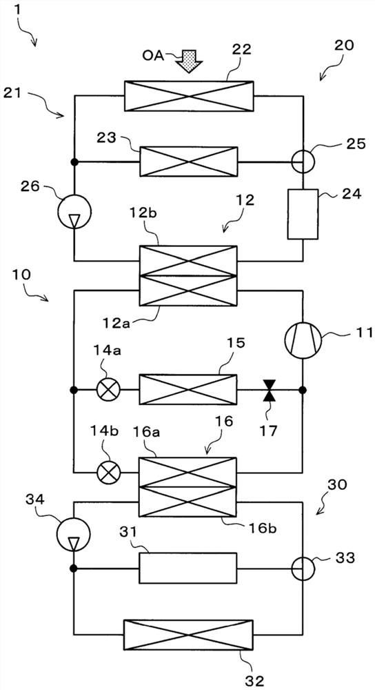
[0032] use Figure 1-7 A first embodiment of the present invention will be described. In the first embodiment, the refrigeration cycle apparatus of the present invention is applied to an air conditioner 1 of an electric vehicle that obtains a driving force for vehicle running by a running electric motor. The air conditioner 1 performs air conditioning of a vehicle interior as a space to be air-conditioned in an electric vehicle, and temperature adjustment of a battery 31 as a heat generating device.

[0033] Furthermore, the air conditioner 1 can switch between the cooling mode, the heating mode, and the dehumidifying and heating mode of the air conditioning operation mode for air conditioning the vehicle interior. The cooling mode is an operation mode in which the blown air blown into the vehicle interior is cooled and blown into the vehicle interior. The heating mode is an operation mode in which the blown air is heated and blown into the vehicle interior. The dehumidific...

no. 2 approach

[0302] Next, based on Figure 8 A second embodiment of the present invention will be described. In the second embodiment, instead of the three-way valve 33 , a low temperature side flow rate regulating valve 33 a is employed as the flow rate regulating part and the heat absorption regulating part of the low temperature side heat medium circuit 30 .

[0303] Such as Figure 8 As shown, the outlet side of the heat medium passage of the battery 31 and the outlet side of the outside air heat exchanger 32 are connected to a low temperature side flow rate regulating valve 33a. The low-temperature-side flow regulating valve 33a is constituted by an electric three-way flow regulating valve having three inflow and outflow ports.

[0304] That is, one of the inflow and outflow ports of the low temperature side flow regulating valve 33a is connected to the exit side of the heat medium passage of the battery 31, and the other inflow and outflow port of the low temperature side flow regu...

no. 3 approach

[0310] Next, refer to Figure 9 A third embodiment of the present invention will be described. In the third embodiment, instead of the three-way valve 33 , the first low-temperature side pump 35 a and the second low-temperature side pump 35 b are used as the flow rate adjustment unit and the heat absorption adjustment unit of the low-temperature side heat medium circuit 30 .

[0311] In addition, in the third embodiment, the low-temperature side pump 34 of the above-mentioned embodiment is abolished along with the adoption of the first low-temperature side pump 35a and the second low-temperature side pump 35b.

[0312] Such as Figure 9 As shown, in the low-temperature-side heat medium circuit 30 of the third embodiment, a heat medium confluence part having a three-way joint structure is arranged at the position of the three-way valve 33 of the first embodiment. The outlet side of the heat medium junction is connected to the inlet of the heat medium passage 16 b in the refri...


PUM


Abstract

A refrigeration cycle device comprises a heat pump cycle (10), a high-temperature-side heat medium circuit (21), and a low-temperature-side heat medium circuit (30). The heat pump cycle has a compressor (11), a high-temperature-side heat medium-refrigerant heat exchanger (12), a heat absorption decompression unit (14b), and a low-temperature-side heat medium-refrigerant heat exchanger (16). The high-temperature-side heat medium circuit has a heat exchanger (23) for heating that exchanges heat between a high-temperature-side heat medium and a fluid of which the temperature is to be adjusted. The low-temperature-side heat medium circuit has a plurality of heat absorption devices (31, 32, 36, 38) that causes heat to be absorbed in a low-temperature-side heat medium flowing out from the low-temperature-side heat medium-refrigerant heat exchanger; and heat absorption amount adjusting parts (33, 33a, 35a, 35b, 37) that change the heat absorption amounts of the low-temperature side heat mediums in the heat absorption devices, respectively. When the heat absorption amount adjusting parts change the heat absorption amounts of the low-temperature side heat mediums in the heat absorption devices, respectively, the refrigeration cycle device reduces the flow rate of a refrigerant flowing into the low-temperature-side heat medium-refrigerant heat exchanger.

Description

[0001] Cross-references to related applications [0002] This application is based on Japanese Patent Application No. 2019-67629 filed on March 29, 2019, and the contents described therein are incorporated herein by reference. technical field [0003] The invention relates to a refrigeration cycle device. Background technique [0004] Conventionally, Patent Document 1 discloses a vehicle air conditioner capable of cooling a secondary battery with low-temperature cooling water generated in an evaporator of a refrigeration cycle. The vehicle air conditioner of Patent Document 1 has a refrigeration cycle, a low water temperature circuit, and a high water temperature circuit, and is configured to be capable of cooling and heating the vehicle interior. The low water temperature circuit in Patent Document 1 is provided with a cooling water flow path for the secondary battery, a low-temperature side radiator for exchanging heat between the cooling water and outside air, and a refr...

Claims


Application Information

Patent Timeline
IPC IPC(8): F25B5/02F25B1/00B60H1/22
CPCF25B1/00F25B5/02B60H1/00899B60H2001/00928B60H2001/00942B60H1/32284B60H1/00278
Inventor 三浦功嗣河野纮明山口素弘谷口和也加藤吉毅牧原正径前田隆宏谷冈邦义冈村徹牧本直也
Owner DENSO CORP
Why Eureka
Try Eureka