Supercharge Your Innovation With Domain-Expert AI Agents!

Cylindrical surface hole forming equipment

A cylindrical surface and hole-forming technology, which is applied in the direction of drilling/drilling equipment, metal processing equipment, boring/drilling, etc., can solve the problems of prolonging the production cycle cost of parts, and achieve saving of processing procedures, simple structure, The effect of improving accuracy

Inactive Publication Date: 2021-11-16
杭州鼎友五金机械制造有限公司
View PDF0 Cites 1 Cited by
  • Summary
  • Abstract
  • Description
  • Claims
  • Application Information

AI Technical Summary

Problems solved by technology

[0003] However, reserving a boss on the surface of a cylindrical part will prolong the production cycle of the part and the process cost of processing the boss after drilling

Method used


Image

  • Cylindrical surface hole forming equipment
  • Cylindrical surface hole forming equipment
  • Cylindrical surface hole forming equipment

Examples


Embodiment Construction

[0038] The accompanying drawings are all schematic diagrams of the implementation of the present invention, so as to understand the principle of structural operation. The specific product structure and proportional size can be determined according to the use environment and conventional technology.

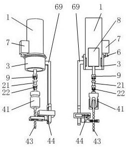
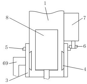
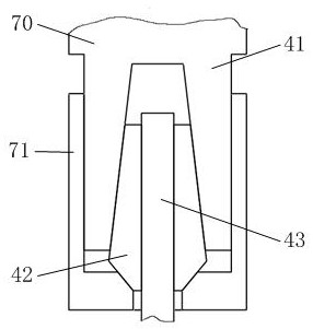
[0039] Such as figure 1 , 2 As shown, it includes mechanical arm 1, electric drive module A7, ring sleeve A3, L rod 69, electric drive module B8, universal joint mechanism A9, connecting rod 21, universal joint mechanism B22, drill bit fixture 41, vibration elimination mechanism 44, where if figure 1 , 3 As shown, the end of the output shaft of the electric drive module B8 installed in the end of the mechanical arm 1 is equipped with a connecting rod 21 through the universal joint mechanism A9, and the connecting rod 21 is equipped with a drill bit for clamping the twist drill bit 43 through the universal joint mechanism B22 Fixture 41; as Figure 6 , 10 As shown, both the u...


PUM


Abstract

The invention belongs to the field of cylindrical surface hole forming, and particularly relates to cylindrical surface hole forming equipment. The equipment comprises a mechanical arm, an electric drive module A, a ring sleeve A, an L rod, an electric drive module B, a universal joint mechanism A, a connecting rod, a universal joint mechanism B, a drill bit clamp and a damping mechanism. The tail end of an output shaft of the electric drive module B mounted in the tail end of the mechanical arm is provided with the connecting rod through the universal joint mechanism A, and the connecting rod is provided with a drill bit clamp for clamping a twist drill bit through the universal joint mechanism B; According to the equipment, stable punching can be directly carried out on the cylindrical surface without reserving a boss with a production end face vertical to a punching axis on the cylindrical surface, so that the cylindrical surface processing procedure is saved, the cylindrical surface punching operation cost is reduced, the cylindrical surface punching cost is effectively reduced, and the cylindrical surface punching efficiency is improved.

Description

technical field [0001] The invention belongs to the field of cylindrical surface hole forming, in particular to a cylindrical surface hole forming equipment. Background technique [0002] During the production and processing of mechanical parts, drills are often used to process round holes on the surface of cylindrical parts that are not perpendicular to the drilling point of the cylinder. During the drilling process, the drill will be elastically bent due to the lateral force of the cylinder. , so that the position of the round hole drilled by the drill bit is offset, resulting in the failure of cylindrical drilling. In addition, the drill bit will break under the lateral force of the cylinder due to irregular use by the user. In order to solve the problem of bending or breaking of the drill bit, a boss whose end face is perpendicular to the axis of the hole to be drilled is generally reserved on the surface of the cylindrical part, and the drill bit is used to punch holes...

Claims


Application Information

Patent Timeline
IPC IPC(8): B23B39/16B23B47/00B23Q11/00
CPCB23B39/161B23B47/00B23Q11/0032
Inventor 任乐涛龚雁董思民
Owner 杭州鼎友五金机械制造有限公司
Features
  • R&D
  • Intellectual Property
  • Life Sciences
  • Materials
  • Tech Scout
  • Unparalleled Data Quality
  • Higher Quality Content
  • 60% Fewer Hallucinations
Learn More