Check patentability & draft patents in minutes with Patsnap Eureka AI!

A laser tracker plane coordinate high precision lofting device and method

A technology of laser tracker and plane coordinates, which is applied in the direction of using optical devices, measuring devices, instruments, etc., can solve problems such as tilt errors, errors, and debris, so as to eliminate coordinate lofting errors, improve accuracy and efficiency, and reduce effect of error

Active Publication Date: 2022-06-07
INST OF MODERN PHYSICS CHINESE ACADEMY OF SCI
View PDF7 Cites 0 Cited by
  • Summary
  • Abstract
  • Description
  • Claims
  • Application Information

AI Technical Summary

Problems solved by technology

There is a problem with this method of stakeout: the target base contacts the stakeout surface. If the stakeout surface is uneven or there are sundries at the bottom of the target base and other factors, it will cause a tilt error of the target base. The target base supports the target ball, because the target base itself The thickness of the laser tracker and the radius of the target ball of the laser tracker will cause the inclination error of the target base to produce a coordinate error of a magnification in the center of the target ball of the laser tracker, and draw a point artificially through the center hole of the target base. The process will also bring errors due to problems such as the alignment of the needle and the hole, and the control of the angle of the needle.
The stakeout error of the position coordinate points of the key components of the accelerator will directly affect the installation accuracy of the accelerator support system. If the stakeout error exceeds the adjustment range of the support system design, it will seriously affect the collimation installation schedule, and then affect the collimation installation of the particle accelerator components. efficiency

Method used


Image

  • A laser tracker plane coordinate high precision lofting device and method
  • A laser tracker plane coordinate high precision lofting device and method
  • A laser tracker plane coordinate high precision lofting device and method

Examples


Embodiment approach

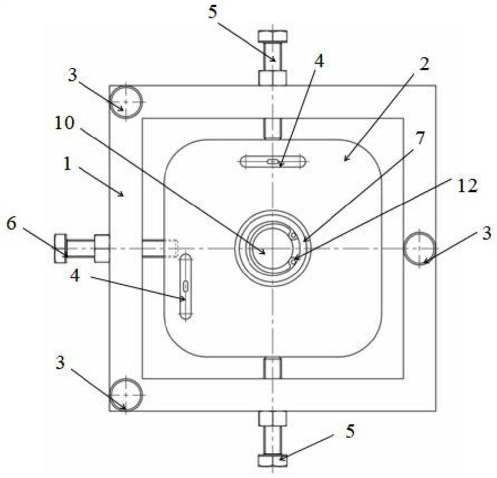
[0048] According to an embodiment of the present invention, the base body 2 is a regular tetrahedron, and two horizontal bubble meters 4 are respectively disposed on adjacent two sides of the base body 2 .

[0049] However, the distance between the horizontal bubble meter 4 and the center of the base body 2 should not be too large, otherwise the overall structure will be too large and complex, the machining accuracy will not be guaranteed, and the cost will be high.

[0050] According to an embodiment of the present invention, the distance between the center of the horizontal bubble meter 4 and the center of the base body 2 is 50±5 mm.

[0051] According to an embodiment of the present invention, the horizontal adjustment part is a horizontal adjustment screw rod 3, the horizontal adjustment screw rod 3 is a group, and the group of horizontal adjustment screw rods 3 is distributed on the periphery of the base 1 to adjust the vertical screw rod Height of different positions of ...

Embodiment 1

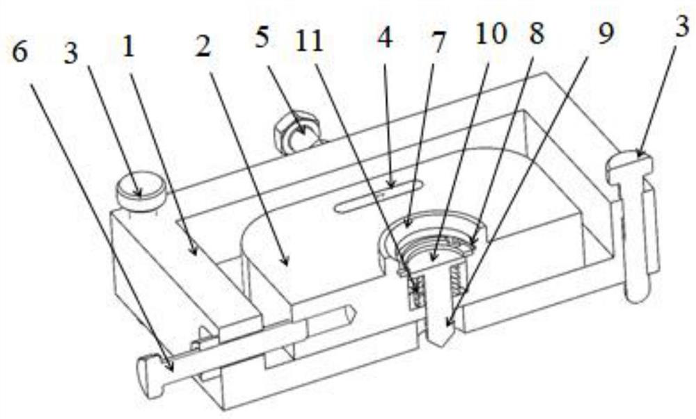
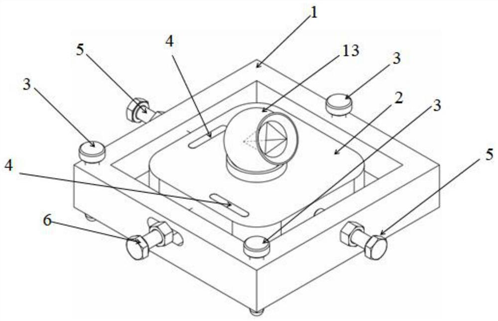
[0086] The embodiment of the present invention discloses a device for high-precision lofting of plane coordinates of a laser tracker, such as Figure 1 to Figure 4 shown.

[0087] The base 1 and the base body 2 of the laser tracker plane coordinate high-precision stakeout device in this embodiment are made of 304 stainless steel, and the shapes are both equilateral quadrilateral structures, wherein each corner of the equilateral quadrilateral of the base body 2 is a chamfered structure.

[0088]At the center of the two adjacent corners of the base 1 of the high-precision lofting device for plane coordinates of the laser tracker and the center of the opposite side of the side where the two corners are located, there are a total of three horizontal adjustment screw rods 3 that can be manually adjusted. The horizontal adjustment screw The rod 3 is made of 304 stainless steel, and is connected to the base 1 through a wire hole, and the upper end is a circular anti-skid knob struct...

Embodiment 2

[0099] This embodiment provides a method for using a laser tracker plane coordinate high-precision stakeout device, using the laser tracker plane coordinate high-precision stakeout device provided in Embodiment 1, the key points of the synchrotron magnet and support system of the heavy ion therapy device are Taking the setting out of the base surface of the synchrotron installation as an example to describe the use method of the high-precision setting out device for the plane coordinates of the laser tracker, the method may include the following steps:

[0100] Step S1 : the laser tracker 14 is installed on the site of the synchrotron of the heavy ion therapy device. The laser tracker 14 is free to set up stations, and the erection position needs to meet enough three-dimensional collimation control points (generally more than 8 control points of different planes) that can measure within a range of about 10m at the same station, and it is also necessary to ensure that the laser ...


PUM


Abstract

The invention relates to a laser tracker plane coordinate high-precision setting out device and method. The device includes: a base body, which is provided with a target ball support portion and an accommodating cavity; a base, which is arranged on the periphery of the base body, is configured to support the base body, and has a constant relative position with the base body in the vertical direction, and a variable relative position in the horizontal direction ; marking assembly, configured to be housed in the accommodation cavity; horizontal adjustment part, configured to be adjustable relative to the base in the vertical direction; position adjustment mechanism, including a horizontal position adjustment device and a longitudinal position adjustment device; a levelness display instrument , including two horizontal bubble instruments whose centerlines along the length direction are perpendicular to each other arranged on the upper surface of the base body, the horizontal or vertical centerline of each horizontal bubble instrument does not pass through the other horizontal bubble instrument. The invention can accurately mark the stakeout coordinates, and improves the accuracy and efficiency of the particle accelerator using the laser tracker to stake out points on the ground.

Description

technical field [0001] The invention relates to the technical field of collimation measurement of particle accelerators, in particular to a device and method for high-precision setting out of plane coordinates of a laser tracker. Background technique [0002] With the continuous improvement of the alignment and installation accuracy of particle accelerator components and the standardized alignment and installation, the alignment and installation of most accelerator components requires a laser tracker and a three-dimensional alignment control network to complete. In the alignment and installation of particle accelerators, a very critical step is to use the laser tracker to set out the geometric center of the accelerator installation components and the main geometric elements of the support system to the theoretical coordinate positions of the accelerator foundation installation ground or embedded parts. The measurement principle of the laser tracker is different from that of ...

Claims


Application Information

Patent Timeline
Patent Type & Authority Patents(China)
IPC IPC(8): G01C15/08G01B11/00G01C9/34
CPCG01C15/08G01B11/002G01C9/34
Inventor 陈文军杨龙郑亚军王少明袁建东孙国珍张旭东张小东
Owner INST OF MODERN PHYSICS CHINESE ACADEMY OF SCI
Features
  • R&D
  • Intellectual Property
  • Life Sciences
  • Materials
  • Tech Scout
  • Unparalleled Data Quality
  • Higher Quality Content
  • 60% Fewer Hallucinations
Learn More