Hybrid excitation permanent magnet reluctance linear motor type control rod driving mechanism

A technology of linear motor and mixed excitation, which is applied in the direction of electric components, nuclear reaction control, structural connection, etc., can solve the problems of difficult manufacturing, mechanical wear, and poor control accuracy of reactor power, so as to improve power control accuracy and broaden speed regulation Range, the effect of not easy demagnetization failure

Pending Publication Date: 2021-11-16
CHONGQING UNIV
View PDF1 Cites 1 Cited by
  • Summary
  • Abstract
  • Description
  • Claims
  • Application Information

AI Technical Summary

Problems solved by technology

[0003] (1) The claw assembly moves frequently, and the mechanical wear is serious, which affects the operating life of the control rod drive mechanism;
[0004] (2) The drive rod makes a stepping movement, and the reactor power control accuracy is poor
Although this structure can realize the up and down movement of the drive rod and the magnetic levitation support, it still has the disadvantages of small lifting force, large volume and difficult manufacturing.

Method used


Image

  • Hybrid excitation permanent magnet reluctance linear motor type control rod driving mechanism
  • Hybrid excitation permanent magnet reluctance linear motor type control rod driving mechanism
  • Hybrid excitation permanent magnet reluctance linear motor type control rod driving mechanism

Examples


Embodiment

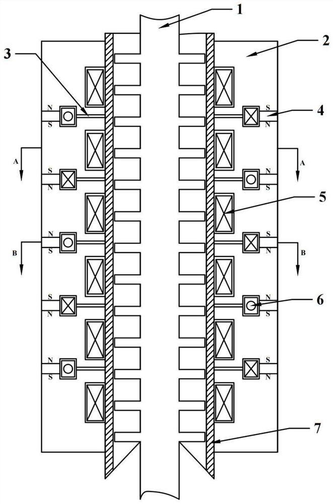
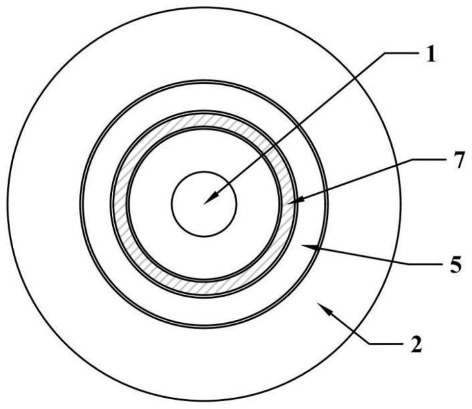
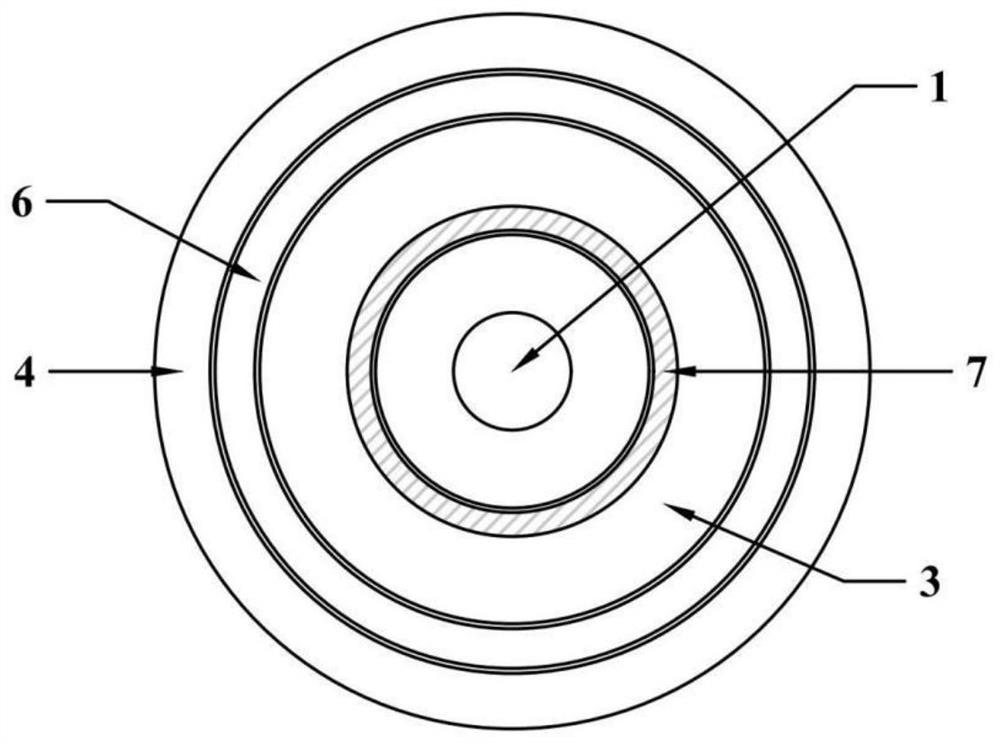
[0035] A hybrid excitation permanent magnet reluctance linear motor type control rod drive mechanism, comprising a cylindrical permanent magnet reluctance linear motor, a holding coil 5 and a pressure-resistant shell 7; the cylindrical permanent magnet reluctance linear motor consists of Drive rod (mover) 1, stator 2, magnetic isolation ring 3, permanent magnet 4 and stator winding 6; drive rod (mover) 1 is located at the innermost layer of the entire mechanism, and stator 2 is located at the outermost layer of the entire mechanism. There is a pressure-resistant shell 7 in the air gap between the driving rod (mover) 1 and the stator 2, and the three are coaxially arranged; the stator 2 includes several stator cores arranged at intervals along the axial direction of the driving rod 1, and the stator cores There is an annular groove on the inner surface, and an annular auxiliary groove is formed between adjacent stator cores. The magnetic isolation ring 3 is embedded in the annul...


PUM


Abstract

The invention relates to a hybrid excitation permanent magnet reluctance linear motor type control rod driving mechanism, awhich belongs to the technical field of linear motor application. The hybrid excitation permanent magnet reluctance linear motor type control rod driving mechanism comprises a driving rod, a stator arranged around the driving rod, and a pressure-resistant shell arranged between the driving rod and the stator.The stator comprises a plurality of stator iron cores arranged at intervals along the axial direction of the driving rod, the inner side surface of the stator iron core is provided with an annular groove, and a holding coil is embedded in the annular groove. Annular auxiliary grooves are formed between the adjacent stator iron cores, stator windings and permanent magnets are embedded in the annular auxiliary grooves, and the magnetizing directions of the adjacent permanent magnets are opposite. The stator winding is connected with a three-phase sine alternating-current power supply, the holding coil is connected with a direct-current power supply, and power-off or power-on states can be kept respectively. The continuous movement of the driving rod is realized, and the power control precision of the nuclear reactor is improved.

Description

technical field [0001] The invention belongs to the technical field of linear motor applications and relates to a hybrid excitation permanent magnet reluctance linear motor type control rod drive mechanism. Background technique [0002] In a nuclear reactor, the control rod drive mechanism is the servo mechanism for power regulation and system protection, and is the only moving device in the reactor structure. Functions such as power adjustment, power maintenance, normal shutdown and emergency shutdown. The traditional magnetic lifting control rod drive mechanism is a step-by-step lifting and lowering, and the movement step is 15.875mm. It mainly has the following disadvantages: [0003] (1) The claw assembly moves frequently, and the mechanical wear is serious, which affects the operating life of the control rod drive mechanism; [0004] (2) The drive rod moves in steps, and the reactor power control accuracy is poor. [0005] In order to solve these problems and adapt t...

Claims


Application Information

Patent Timeline
Patent Type & Authority Applications(China)
IPC IPC(8): H02K41/03H02K11/00G21C7/12
CPCH02K41/031H02K11/0094G21C7/12Y02E30/30
Inventor 徐奇伟杨云王倩李少林王诗雅
Owner CHONGQING UNIV
Why Eureka
Try Eureka