Filter capacitor rapid discharge circuit of numerical control power supply
A digitally controlled power supply and filter capacitor technology, applied in the field of power supply, can solve the problems of long adjustment time and achieve the effect of shortening the adjustment time and improving discharge efficiency
- Summary
- Abstract
- Description
- Claims
- Application Information
AI Technical Summary
Problems solved by technology
Method used
Image

Examples
Embodiment 1
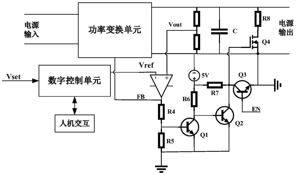
[0026] The main idea of the present invention is that, based on the problem that the adjustment time is long when the output voltage suddenly drops from a high value to a low value, the present invention adds a fast discharge circuit for the filter capacitor in the numerical control unit, and the discharge circuit includes a signal comparison branch , the control branch, and the discharge branch, determine whether the voltage drops through the signal comparison branch, and output a control signal for the discharge of the discharge branch through the control branch after the drop, and then control the discharge branch to discharge. The present invention discharges the filter capacitor in time through the discharge circuit, shortening the adjustment time when the voltage drops.
[0027] Specifically, the fast discharge circuit of the filter capacitor of the digital control power supply is as follows: figure 1 As shown, it includes a signal comparison branch, a control branch, ...
Embodiment 2
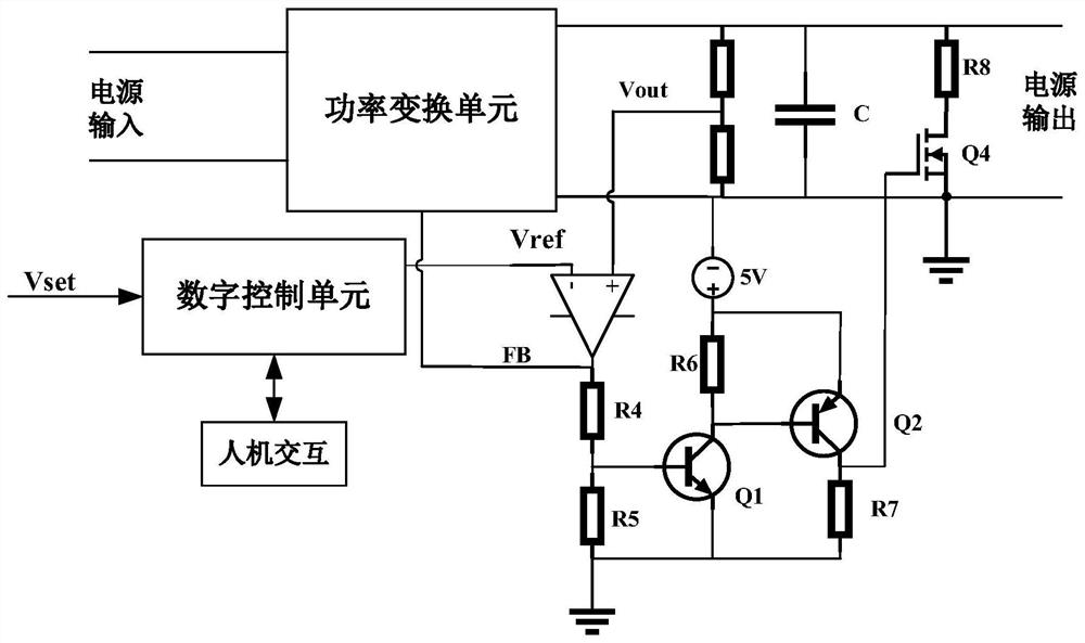
[0040] The difference between the fast discharge circuit of the filter capacitor of the digital control power supply in this embodiment and the embodiment 1 is that the control branch adopts two triodes, and on the basis of the embodiment 1, the number of triodes is reduced, and the circuit is further simplified. save costs.
[0041] Specifically, the fast discharge circuit of the filter capacitor of the numerically controlled power supply in this embodiment is as follows: figure 2 As shown, it includes a signal comparison branch, a control branch, and a discharge branch.
[0042] The signal comparison branch and the discharge branch are the same as those in Embodiment 1, and will not be repeated here.
[0043] The control circuit includes a transistor Q1 and a transistor Q2. The transistor Q1 is an NPN transistor, and the transistor Q2 is a PNP transistor. The base of the transistor Q1 is connected to a voltage divider, and the collector of the transistor Q1 is connected to...
PUM
 Abstract
Description
Claims
Application Information
 - R&D
- Intellectual Property
- Life Sciences
- Materials
- Tech Scout
- Unparalleled Data Quality
- Higher Quality Content
- 60% Fewer Hallucinations
Browse by: Latest US Patents, China's latest patents, Technical Efficacy Thesaurus, Application Domain, Technology Topic, Popular Technical Reports.
© 2025 PatSnap. All rights reserved.Legal|Privacy policy|Modern Slavery Act Transparency Statement|Sitemap|About US| Contact US: help@patsnap.com