An insulation and heat insulation protective wire structure for mechanical equipment

A technology of insulation, heat insulation and mechanical equipment, applied in welding equipment, laser welding equipment, metal processing equipment, etc., can solve problems such as wire winding, and achieve the effect of improving operating efficiency

Active Publication Date: 2021-12-21
JINTAN HUARONG INSULATING MATERIAL CO LTD
View PDF6 Cites 0 Cited by
  • Summary
  • Abstract
  • Description
  • Claims
  • Application Information

AI Technical Summary

Problems solved by technology

[0003] At present, semi-automatic laser welding machines are widely used, but semi-automatic laser welding machines come with long wires. In order to facilitate the staff to weld steel or other metals, the length and strength of the wires on the semi-automatic welding machine are extremely important. However, at present, the wires that come with the semi-automatic welding machine are all wound on the device, which will bring a certain amount of trouble and difficulty to the user during use and even after use.

Method used


Image

  • An insulation and heat insulation protective wire structure for mechanical equipment
  • An insulation and heat insulation protective wire structure for mechanical equipment
  • An insulation and heat insulation protective wire structure for mechanical equipment

Examples


Embodiment 1

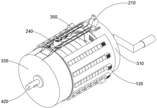
[0048] Combine Figure 3-8 As shown, the insulating insulation of the mechanical device provided by the present invention includes a dust collecting mechanism 100, a wire guide mechanism 200, a reinforcing cyclone mechanism 300, and a torsion control mechanism 400, and the dust collecting mechanism 100 is mounted on the reinforcing cyclone mechanism 300. The wire guiding mechanism 200 is mounted outside the reinforcing cyclone mechanism 300, in addition, the torsion control mechanism 400 is actively connected inside the reinforcing cyclone mechanism 300.

[0049] The dust collecting mechanism 100 includes a protective outer cover 110 and a athale combination 120, and the atmospheric combination 120 also includes an exhaust tank 121 and a negative ion electrode 122, and the wire guide mechanism 200 includes a positioning cover 210, an inner pad ring 220, a nut 230, a limited outer shelf 240 The axial ring 250, the guide rod 260, the spherical bun 270, the anti-competent pipe 280, an...

Embodiment 2

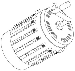
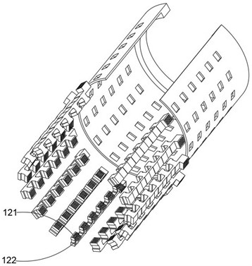
[0052] Combine image 3 and 4 As shown, on the basis of the first example, the attachment of the outer casing 330 is attached to the outer casing 330 by using the protective housing 110, and combined with a plurality of annular distribution of air gas combination 120 to the strong contaminant in the device, there is greatly improved wires. Protected and the inside of the exhaust tank 121 is opened three-to-air, and the device is connected to the outside environment with the exterior environment, thereby facilitating the rapid removal of dust or contaminants, and the dust collecting mechanism 100 also includes mounting in protection. The athabird combination 120 on the inside of the outer cover 110, and the atmosphere combination 120 is a ring-shaped state of the lumen side wall along the protective outer cover 110, and the air gas combination 120 also includes an insulating venting groove 121 and an negative ion electrode 122 mounted in the exhaust tank 121. And there is three sets...

Embodiment 3

[0054] Combine Image 6 As shown in the above embodiment, by the guidance toward the wires by the positioning cover 210, it is possible to enable the safety of the wire to wind, and two anti-compensation pipes 280 are installed in the top and bottom ends of the inner cavity of the spherical bin bin 270. Using the protection of the wire, the maintenance of the wire is protected or the wear during the stretching or collapse of the wire, and the central portion of the inner pad 220 is opened, and the inner pad ring 220 pair is used. The wire outer insulating layer increases the frictional resistance, which can control the stability of the wire stretching and winding period. When the wire passes through the lumen of the wire, the two silica rubil circles can be greatly reduced. The wear of the insulating layer, the wire guiding mechanism 200 also includes a positioning cover 210 mounted on the outer casing 330, a nut 230 connected to the positioning cover 210 and an inner pad 220 mount...


PUM


Abstract

The invention discloses an insulating and heat-insulating protective wire structure for mechanical equipment, which includes a dust-reducing mechanism, a wire guiding mechanism, a reinforced turning mechanism and a torsion control mechanism. The wire guide mechanism includes a limit outer frame, a collar built in the middle of the limit outer frame, a guide rod connected in the collar, and a safety frame installed outside the limit outer frame. The mechanism includes an outer casing for supplying air to the wire being wound and a wire harness located inside the outer casing. Install a stabilizing gasket in the inner cavity of the harness, and install a torsion spring on the inner side of the stabilizing gasket, use the rocker outside the rotating transmission rod to drive the inner shaft and give the torsion spring an increase in torque, use the pull and push of the inner shaft and The transmission rod is used to control the transmission and automatic recovery of the wires inside the harness, which can greatly improve the operating efficiency of the user.

Description

Technical field [0001] The present invention relates to the field of mechanical equipment cable protection technology, and is specifically a mechanical device insulating insulation line structure. Background technique [0002] With the rapid development of the social manufacturing industry, people began using a large number of mechanical equipment to replace the artificial high-difficult steel frame structure welding operation, especially today's use of laser welding machines, according to the application field, in manufacturing, powder In the fields of metallurgy, automotive industry, electronics industry, and biomedical, laser welding machines are also divided into semi-active and fully automated. [0003] At present, the use of semi-automated laser welding machines is relatively wide, but the semi-automated laser welding opportunity comes with a longer wire, in order to facilitate the staff of steel or other metals, the length and strength of the lead wire on the semi-automate...

Claims


Application Information

Patent Timeline
Patent Type & Authority Patents(China)
IPC IPC(8): B23K26/70H02G11/02
CPCB23K26/702H02G11/02
Inventor 陆帮荣
Owner JINTAN HUARONG INSULATING MATERIAL CO LTD
Why Eureka
Try Eureka