Automatic installing and positioning device for large-diameter shaft parts for lathe

A shaft part, automatic installation technology, applied in positioning devices, large fixed members, metal processing machinery parts and other directions, can solve the problems of low positioning and installation efficiency, high labor intensity, etc., to achieve simple structure, convenient installation, saving man-hours and The effect of human labor

Pending Publication Date: 2021-11-19
HUANGHE S & T COLLEGE
10 Cites 0 Cited by

AI-Extracted Technical Summary

Problems solved by technology

At present, the labor intensity of skilled workers is high,...

Method used

In the present embodiment, as shown in Figure 2, split nut control pin 15 is set on split nut 14, the lower end of split nut control pin 15 connects split nut 14, and its upper end passes mobile frame structure 12 and The helical groove on the circumferential surface of the split nut control shaft 11 cooperates. Therefore, when the split nut control shaft 11 rotates, the split nut control pin 15...

Abstract

An automatic installing and positioning device for large-diameter shaft parts for a lathe comprises a power mechanism, a spiral lead screw and at least two sets of shaft supporting mechanisms, wherein each set of shaft supporting mechanism comprises a split nut, an opening and closing driving assembly, a moving frame and a lifting frame, and the opening and closing driving assemblies are used for controlling opening and closing nuts and the spiral lead screw to be disengaged or engaged, so that power transmission or power separation of the spiral lead screw and the shaft supporting mechanisms is achieved. According to the scheme, the shaft parts with different diameters are rapidly positioned through lifting of a lifting frame structure, a servo motor drives the two shaft part supporting structures to horizontally move through the spiral lead screw, the shaft parts are driven to horizontally move, and therefore the parts and a lathe chuck can be rapidly installed in a butt joint mode; and opening and closing of the split nuts are adjusted through a control assembly, cutting off and closing of power between the spiral lead screw and the shaft part supporting structures are achieved, therefore, adjustment of the distance between two sets of the shaft parts is achieved, and positioning and supporting of parts with different lengths are achieved.

Application Domain

Large fixed membersPositioning apparatus +2

Technology Topic

Moving frameServo +3

Image

  • Automatic installing and positioning device for large-diameter shaft parts for lathe
  • Automatic installing and positioning device for large-diameter shaft parts for lathe
  • Automatic installing and positioning device for large-diameter shaft parts for lathe

Examples

  • Experimental program(1)

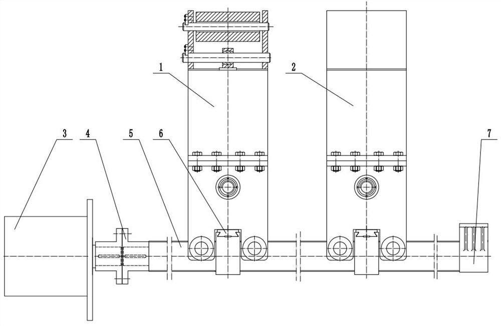
Example Embodiment

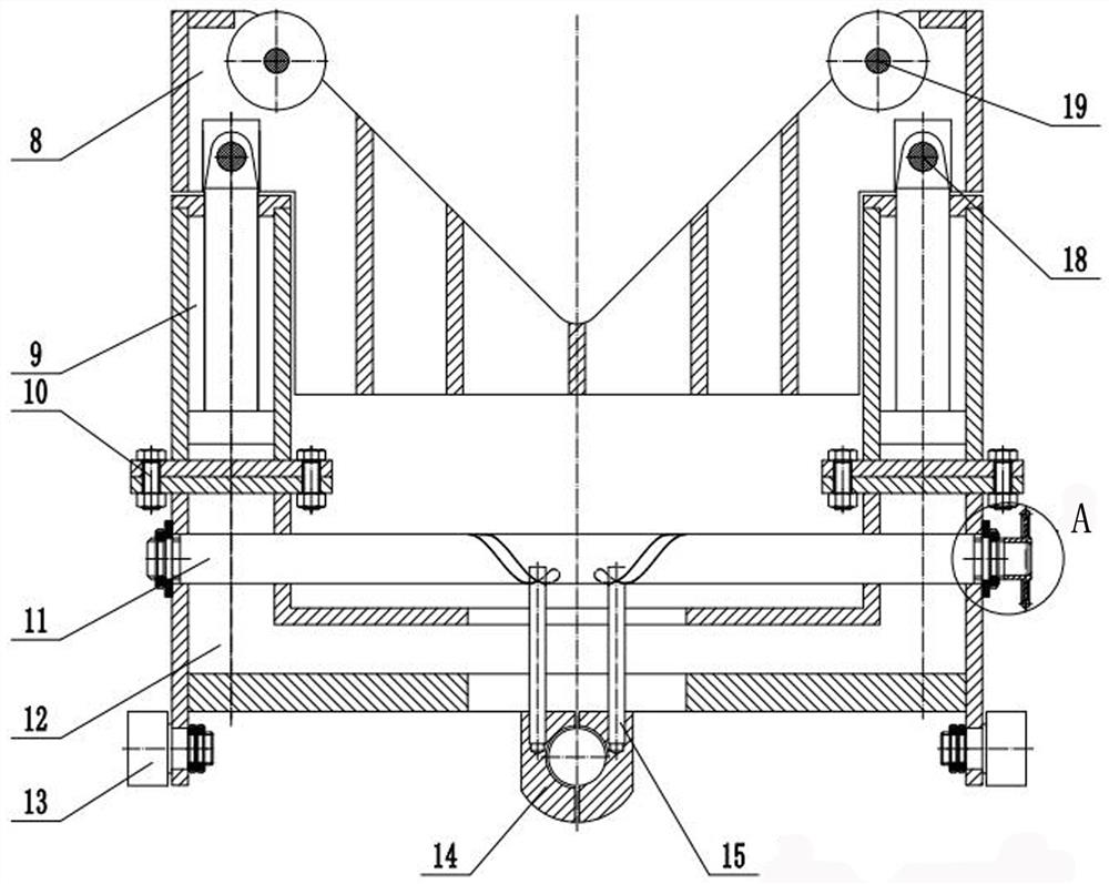
[0021] Hereinafter, the present invention will be specifically described through exemplary embodiments. It should be understood, however, that elements, structures and features of one embodiment may be beneficially combined in other embodiments without further recitation.
[0022] It should be noted that: unless otherwise defined, the technical terms or scientific terms used herein should have the usual meanings understood by those with ordinary skill in the art to which the present invention belongs. The terms "first", "second" and similar terms used in the description of the patent application and the claims of the present invention do not denote any order, quantity or importance, but are only used to distinguish different components. Likewise, words like "a," "an," or "the" do not denote a quantitative limitation, but rather denote the presence of at least one. Similar words like "include" or "include" indicate that the elements or items appearing before "including" or "include" cover the elements or items listed after "including" or "including" and their equivalents, but do not exclude other component or object.
[0023] Attached below Figure 1-3 The detailed structure of this embodiment is described:
[0024] This embodiment is described by setting two shaft support mechanisms as an example: figure 1 As shown, an automatic installation and positioning device for large-diameter shaft parts for lathes includes a first shaft support mechanism 1, a second bearing support mechanism 2, a screw screw 5, a servo motor 3, a coupling 4, and a screw fixing device 7. The power output end of the servo motor 3 is connected to one end of the screw screw through the coupling 4, and the other end of the screw screw is rotated and set on the screw fixing device 7. The first shaft support mechanism 1 and the second bearing support mechanism 2 are respectively Set on the screw 5 and driven by the servo motor 3 .
[0025] The first shaft support mechanism 1 and the second bearing support mechanism 2 described above have the same structure, such as figure 2 As shown, each set of shaft support mechanisms is mainly composed of a lifting frame 8, a lifting assembly 9, a moving frame 12, an opening and closing nut 14, an opening and closing nut control pin 15, an opening and closing nut control shaft 11, a roller bearing 13, a connecting bolt 10, a guide rail 6. The adjusting nut 16, the supporting roller 19, and the control shaft rotating handwheel 17 are composed; the opening and closing nut control shaft 11, the control shaft rotating handwheel 17, the opening and closing nut control pin 15 and the guide rail 6 are installed on the moving frame. The opening and closing drive assembly for controlling the opening and closing nut 14 to disengage or engage with the screw screw 5 .
[0026] In this embodiment, as figure 2 As shown, the moving frame 12 has a concave-shaped structure, and the lower end of the lifting frame 8 has a convex portion that matches the concave-shaped structure, and is clamped on the upper end of the moving frame 12 through the convex portion, and the lifting components 9 are distributed on the moving frame. On both sides of 12, the lower end of the lifting assembly 9 is connected and fixed with the moving frame structure 12 by connecting bolts 10, and the upper end is connected with the lifting frame 8 through the pin shaft 18; in this embodiment, the lifting assembly 9 adopts a hydraulic cylinder.
[0027] In this embodiment, as figure 2 As shown, two sets of roller bearings 13 are provided on both sides of the bottom end of the mobile frame structure 12, and a set of open and close nuts 14 are provided in the middle of the bottom to cooperate with the screw screw 5, and the open and close nuts 14 are connected to the mobile frame structure 12 through the guide rails 6. connect.
[0028] In this embodiment, as figure 2 As shown, the opening and closing nut 14 is provided with an opening and closing nut control pin 15, the lower end of the opening and closing nut control pin 15 is connected to the opening and closing nut 14, and its upper end passes through the moving frame structure 12 and the opening and closing nut control shaft 11 The screw on the circumferential surface of the shaft 11 Therefore, when the opening and closing nut control shaft 11 rotates, the opening and closing nut 14 is driven to move along the guide rail by the opening and closing nut control pin 15 to realize the disengagement or engagement of the opening and closing nut and the screw screw.
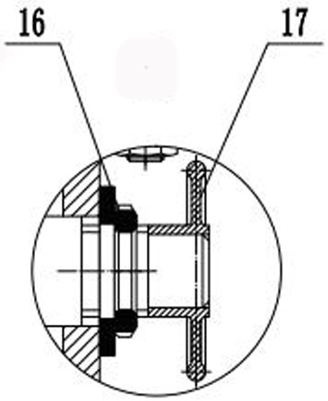
[0029] In this embodiment, as image 3 As shown, both ends of the opening and closing nut control shaft 11 are connected with the moving frame structure 12 through the adjusting nut 16 , and one end of the opening and closing nut control shaft 11 is connected to the control shaft rotating handwheel 17 .
[0030] The specific installation process of the present invention is as follows:
[0031] like figure 1 As shown, the right end of the screw screw 5 is fixedly connected with the lathe bed through the screw fixing device 7, the servo motor 3 is fixedly connected with the machine bed through its own flange, and the servo motor 3 transmits the power through the coupling 4. To the screw screw 5, the screw screw 5 is connected to the opening and closing nut 14 at the bottom of the first shaft support mechanism 1 and the second shaft support mechanism 2. At this time, the opening and closing nut 14 and the screw screw 5 are in an engaged state, driving the first shaft support mechanism 1. The shaft support mechanism 1 and the second shaft support mechanism 2 move simultaneously.
[0032] like figure 2 As shown, by controlling the control shaft in the first shaft support mechanism 1 or the control shaft in the second shaft support mechanism 2 to rotate the handwheel 17, the control shaft 11 of the opening and closing nut is driven to rotate, and the spiral groove on the surface of the control shaft 11 of the opening and closing nut drives the two opening and closing The nut control pin 15 translates to both sides, the translation of the opening and closing nut control pin 15 drives the opening and closing nut 14 to separate to both sides, and the opening and closing nut 14 and the screw screw 5 are in a disengaged state, then the first shaft support mechanism 1 or the second The two-axis support mechanism 2 will not translate with the rotation of the screw 5, so as to achieve the purpose of adjusting the distance between the first-axis support mechanism 1 and the second-axis support mechanism 2 and adapting to the positioning and installation of parts with different lengths .
[0033] like figure 2 As shown, two support rollers 19 are installed on the upper part of the first shaft support mechanism 1 and the second shaft support mechanism 2 to bear the weight of the parts, and can follow the rotation of the parts to reduce friction.
[0034] like figure 2 As shown, in the first shaft support mechanism 1 and the second shaft support mechanism 2, there are two sets of roller bearings 13 on both sides of the bottom end of the moving frame 12, and the roller bearings 13 are pressed on the guide rails of the lathe bed.
[0035] like figure 2As shown, in the first shaft support mechanism 1 and the second shaft support mechanism 2, the moving frame 12 and the lifting frame 8 are connected through the hydraulic cylinder 9, the hydraulic cylinder 9 is fed with hydraulic oil, the piston rod starts to rise and fall, and the lifting frame structure is driven by the pin shaft 18. 8. Lift up and down, so as to ensure that the shaft parts on the first shaft support mechanism 1 and the second shaft support mechanism 2 are aligned with the lathe chuck.
[0036] It should be noted that the above-mentioned embodiment takes the provision of two shaft support mechanisms as an example. Of course, when the processed bearing parts are large and long, those skilled in the art can also set up three or more as required.
[0037] It should be noted that although the present invention has been described by the above-mentioned embodiments, the present invention may also have other various embodiments. Without departing from the spirit and scope of the present invention, those skilled in the art can obviously make various corresponding changes and modifications to the present invention, but these changes and modifications should belong to the appended claims of the present invention and their equivalents within the scope of protection.

PUM

no PUM

Description & Claims & Application Information

We can also present the details of the Description, Claims and Application information to help users get a comprehensive understanding of the technical details of the patent, such as background art, summary of invention, brief description of drawings, description of embodiments, and other original content. On the other hand, users can also determine the specific scope of protection of the technology through the list of claims; as well as understand the changes in the life cycle of the technology with the presentation of the patent timeline. Login to view more.

Similar technology patents

Body condition measuring device

InactiveUS20050234351A1simple structure
Owner:DENSO CORP

Magnetic cooling apparatus and control method thereof

ActiveUS20130180263A1simple structure
Owner:SAMSUNG ELECTRONICS CO LTD

Dual-Drivetrain of Power-Assist Vehicle

InactiveUS20100181130A1enhance uphill momentumsimple structure
Owner:CHOU WEN CHENG

Classification and recommendation of technical efficacy words

  • Simple structure
  • Easy to install

Sharing system for air-conditioning coat

InactiveCN107440179ASimple structureeasy to wear
Owner:QINGDAO HAIER AIR CONDITIONER GENERAL CORP LTD

Feeding device of sorter of batteries plate

InactiveCN101357717ASimple structurecooperate well
Owner:NANJING NORMAL UNIVERSITY

Emergency parachuting device and method for multiple-rotor unmanned aerial vehicle

InactiveCN103895870Aavoid aircraft crashSimple structure
Owner:SOUTH CHINA AGRI UNIV +1

Cooking electric appliance

PendingCN107647763AEasy to installAvoid insulation loss
Owner:FOSHAN SHUNDE MIDEA ELECTRICAL HEATING APPLIANCES MFG CO LTD

System for monitoring vibration of rotating machinery rolling bearing in wireless mode

InactiveCN102053016Ameasurementanalysisdatareal-timeEasy to install
Owner:JIANGSU UNIV
Why Eureka
Try Eureka