Eureka AIR delivers breakthrough ideas for toughest innovation challenges, trusted by R&D personnel around the world.

Method and system for decontaminating retrograde condensation zone of target well

A target well, condensate technology, applied in liquid/gas jet drilling, directional drilling, earthwork drilling and production, etc., can solve the problems of difficult gas communication, discount of anti-condensation removal effect, short validity period of anti-condensation removal, etc. Achieve the effect of decontamination and long validity period

Pending Publication Date: 2021-11-19
CHINA PETROLEUM & CHEM CORP
View PDF0 Cites 0 Cited by
  • Summary
  • Abstract
  • Description
  • Claims
  • Application Information

AI Technical Summary

Problems solved by technology

For the reverse condensate pollution produced in the later stage of production of the fractured well, after the circular gas injection, the gas will extend along the artificial fracture to the direction of the maximum horizontal principal stress, and then, the reverse condensate pollution area near the artificial fracture along the direction of the maximum horizontal principal stress The interfacial tension of internal condensate oil and gas is reduced, the gas phase permeability and the flow state of condensate oil are improved, so the reverse condensation damage can be effectively relieved, but it is difficult for the gas to communicate with the reservoir far away from the direction of the maximum horizontal principal stress, resulting in a The oil ring near the direction cannot be removed, the overall anti-condensation removal effect is greatly reduced, and the effective period of anti-condensation removal is short

Method used


Image

  • Method and system for decontaminating retrograde condensation zone of target well
  • Method and system for decontaminating retrograde condensation zone of target well
  • Method and system for decontaminating retrograde condensation zone of target well

Examples


Embodiment Construction

[0025] Specific embodiments of the present invention will be described in detail below in conjunction with the accompanying drawings. It should be understood that the specific embodiments described here are only used to illustrate and explain the present invention, and are not intended to limit the present invention.

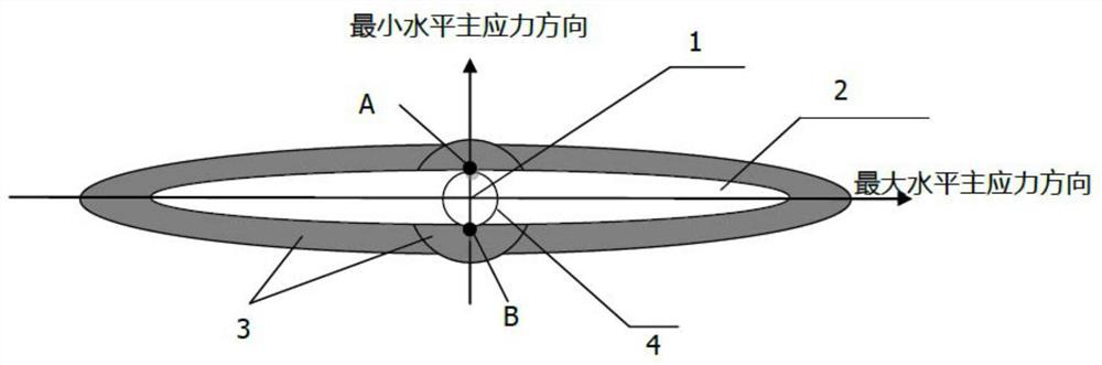
[0026] Before introducing specific embodiments of the present invention, a brief introduction will be made to the anti-condensation area of ​​the target well. like figure 1 As shown, an anti-condensation zone 3 is formed around the wellbore 1 (or casing 4) and the original artificial fracture 2 of the target well. Wherein, the original artificial fracture 2 is located on the outside of the casing 4 around the wellbore 1. Viewed along the direction of the minimum horizontal principal stress, the edge of the original artificial fracture 2 may just be located at the outer wall of the casing 4, or may be at a distance from The outer wall of the casing 4 has a cert...


PUM


Abstract

The invention relates to the technical field of gas reservoir development, and discloses a method and system for decontaminating a retrograde condensation zone of a target well. The method comprises the steps that windowing sidetrack drilling is carried out on a casing pipe of the target well and the retrograde condensation zone located around an original artificial fracture in the preset direction of a target reservoir stratum where the target well is located; the original artificial fracture is fractured to form a new artificial fracture with a perforation; a carrying fluid carrying a plugging object is injected into the new artificial fracture to temporarily plug the perforation on the new artificial fracture within a preset range along the maximum horizontal principal stress direction of the target reservoir; and fracturing is carried out on the retrograde condensation area subjected to sidetrack drilling, so that a crack system is formed in the retrograde condensation area, the crack system communicates with a new artificial crack after the plugging object flows back along with the carrying fluid, and condensate oil in the retrograde condensation area flows into the new artificial crack through the crack system. According to the method for decontaminating the retrograde condensation zone of the target well, the pollution of the whole retrograde condensation area can be effectively removed, and the decontaminating effective period is long.

Description

technical field [0001] The invention relates to the technical field of gas reservoir development, in particular to a method and system for decontaminating the anti-condensation area of ​​a target well. Background technique [0002] At present, tight sandstone condensate gas reservoirs are usually developed by fracturing. After depletion development, as the formation pressure drops below the dew point pressure, retrograde condensation areas (or reverse condensation pollution ( damage) belt). For water-producing tight sandstone condensate gas reservoirs, as the gas phase permeability decreases, the liquid-carrying capacity of the gas decreases, and formation water and condensate oil accumulate near the wellbore and near the original artificial fractures to form retrograde condensation areas (or reverse condensation regions). analysis damage zone), the formation gas cannot pass through the damage zone, and finally the gas well cannot be drilled. For example, in a well 1-10 in...

Claims


Application Information

Patent Timeline
Patent Type & Authority Applications(China)
IPC IPC(8): E21B7/04E21B7/18E21B29/06E21B43/26E21B33/13E21B43/267
CPCE21B7/04E21B7/18E21B29/06E21B43/26E21B43/261E21B43/267
Inventor 张冲杨靖李晓东王娟娟邵立民缪明铭夏富国宋宪实
Owner CHINA PETROLEUM & CHEM CORP
Why Eureka
Eureka Blog
Learn More