
Pipeline leakage monitoring method based on fiber bragg grating temperature measurement technology

A fiber grating and technology technology, which is applied in the field of pipeline leakage monitoring based on fiber grating temperature measurement technology, can solve the problems of surrounding temperature sensing leakage points, leakage points difficult to pipeline vibration, and inability to perceive through vibration, etc., and the cost is achieved. Low, high sensitivity, practical effect

Pending Publication Date: 2021-11-19
安徽复盛信息科技有限公司
View PDF8 Cites 0 Cited by
  • Summary
  • Abstract
  • Description
  • Claims
  • Application Information

AI Technical Summary

Problems solved by technology

[0004] Conventional pipeline leakage monitors pipeline leakage by sensing changes in soil temperature around the pipeline caused by pipeline leakage. Because the leakage process is slow, it takes a certain amount of time and a certain amount of leakage to affect the soil around the leakage point, causing the soil here The temperature is different from the temperature in other areas. This method takes a long time to sense and has low accuracy. It can only provide a range of values ​​and is difficult to locate accurately. If it is a suspended pipeline, it is difficult to sense the leak point through the surrounding temperature, and the leak point Difficult to cause pipeline vibration, can not be sensed by vibration

Method used


Image

  • Pipeline leakage monitoring method based on fiber bragg grating temperature measurement technology
  • Pipeline leakage monitoring method based on fiber bragg grating temperature measurement technology

Examples


Embodiment 1

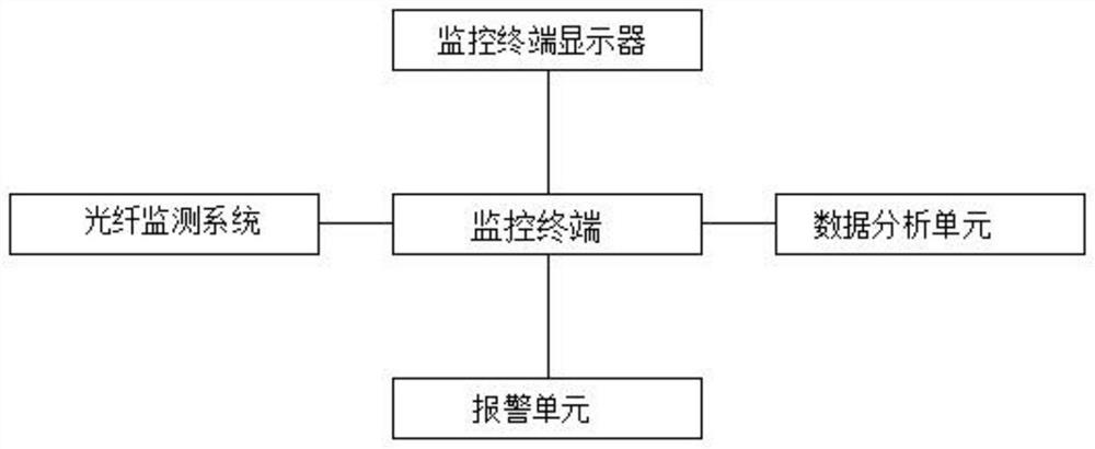
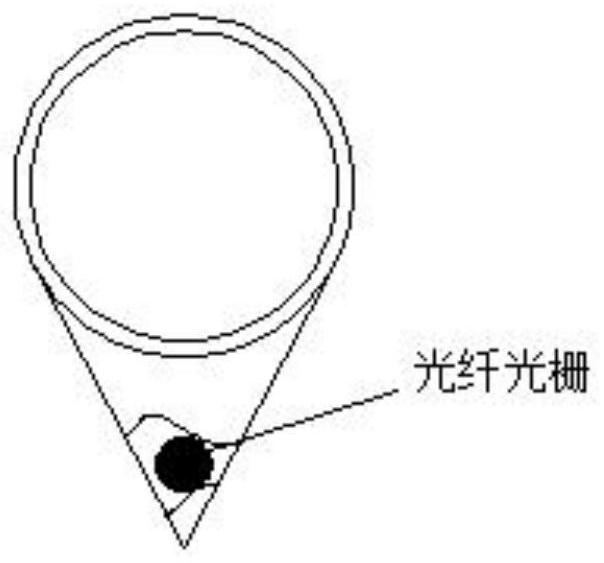
[0029] see Figure 1~2 , in an embodiment of the present invention, a pipeline leakage monitoring method based on fiber Bragg grating temperature measurement technology, comprising the following steps:

[0030] Step 1: lay a V-shaped groove on the bottom surface of the pipeline for receiving water droplets, lay the fiber grating in the groove inside the V-shaped groove, and lay it along the direction of the pipeline;

[0031] Step 2: The light source of the optical fiber monitoring system transmits signals to the optical fiber in step 1 through the amplifier, and uses the back Rayleigh scattering signal generated when the laser is transmitted in the optical fiber to sense the position of the optical fiber grating during the transmission process. Abnormal signals caused by temperature changes;

[0032] Step 3: Send the abnormal pulse information obtained in step 2 to the monitoring terminal, and display the stored temperature pulse signal WT of each temperature domain of the f...

Embodiment 2

[0043] see Figure 1~2 , in an embodiment of the present invention, a pipeline leakage monitoring method based on fiber Bragg grating temperature measurement technology, comprising the following steps:

[0044] Step 1: lay a V-shaped groove on the bottom surface of the pipeline for receiving water droplets, lay the fiber grating in the groove inside the V-shaped groove, and lay it along the direction of the pipeline;

[0045] Step 2: The light source of the optical fiber monitoring system transmits signals to the optical fiber in step 1 through the amplifier, and uses the back Rayleigh scattering signal generated when the laser is transmitted in the optical fiber to sense the position of the optical fiber grating during the transmission process. Abnormal signals caused by temperature changes;

[0046] Step 3: Transmit the abnormal pulse information obtained in step 2 to the monitoring terminal, display the stored temperature pulse signal WT1 of each temperature domain of the ...


PUM

PropertyMeasurementUnit
Snraaaaaaaaaa

Abstract

The invention discloses a pipeline leakage monitoring method based on a fiber bragg grating temperature measurement technology, which comprises the steps: a V-shaped groove for receiving water drops in the bottom surface of a conveying pipeline is laid, and a fiber bragg grating is laid in a groove surface in the V-shaped groove; a light source of an optical fiber monitoring system transmits signals to optical fibers in the first step through an amplifier, and abnormal signals caused by temperature changes in the transmission process are sensed through back Rayleigh scattering signals generated when laser is transmitted in the optical fibers and the arrangement position of the fiber bragg grating; and abnormal pulse information obtained in the step 2 is transmitted to a monitoring terminal, the abnormal pulse information is independently compared with pulse signals normally transmitted by optical fibers and recorded in the monitoring terminal, and pipeline leakage monitoring is achieved. According to the pipeline leakage monitoring method based on the fiber bragg grating temperature measurement technology provided by the invention, two adjacent temperature monitoring points of the fiber bragg grating form a temperature domain, According to different wave band signals of the temperatures of the adjacent temperature domains on the monitoring terminal, a leakage point is positioned, and especially for a suspended pipeline, the leakage point of the pipeline can be effectively measured.

Description

technical field [0001] The invention belongs to the technical field of optical fiber leakage monitoring, in particular to a pipeline leakage monitoring method based on fiber grating temperature measurement technology. Background technique [0002] Pipe gallery pipeline refers to the centralized arrangement of municipal public pipelines such as electricity, communication, gas, water supply and drainage, and heat in the same underground tunnel space for comprehensive development and utilization, so as to save urban construction land, facilitate unified planning and management, and beautify the city. landscape. The unified planning of public pipelines for pipe gallery pipelines can effectively reduce the impact of frequent excavation of pipeline accidents on road surface quality and the environment, while shortening the construction period and improving space utilization. Its comprehensive technical and economic benefits are much higher than the increased initial construction i...

Claims


Application Information

Patent Timeline
IPC IPC(8): F17D5/06G01K11/3206G01K11/324
CPCF17D5/06F17D5/005G01K11/3206G01K11/324
Inventor 许鲁亮施海仁高东东
Owner 安徽复盛信息科技有限公司
Learn More