
Gravity steel ball displacement type automatic energy storage power station and working method

An energy storage power station, displacement technology, applied in the direction of electric energy storage system, energy industry, electrical components, etc., can solve the problems of battery cell defects, waste of environmental resources, unreliable battery management system, etc., to achieve commercial value and social High value, wide site requirements, and the effect of automatic operation

Pending Publication Date: 2021-11-19
XIAN THERMAL POWER RES INST CO LTD
View PDF0 Cites 0 Cited by
  • Summary
  • Abstract
  • Description
  • Claims
  • Application Information

AI Technical Summary

Problems solved by technology

[0004] From the perspective of safety management, the safety of battery energy storage has been listed as a specific fire protection target. The statistical results of fire accidents in global battery energy storage power stations show that defective battery cells and unreliable battery management systems can easily lead to fire accidents. waste of environmental resources

Method used


Image

  • Gravity steel ball displacement type automatic energy storage power station and working method
  • Gravity steel ball displacement type automatic energy storage power station and working method
  • Gravity steel ball displacement type automatic energy storage power station and working method

Examples


Embodiment Construction

[0025] The present invention will be described in further detail below in conjunction with the accompanying drawings and specific embodiments.

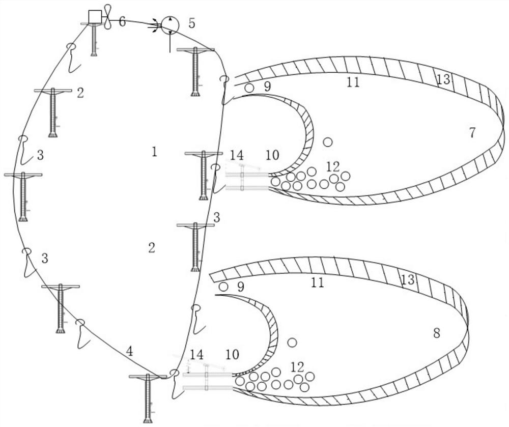
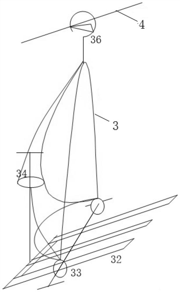
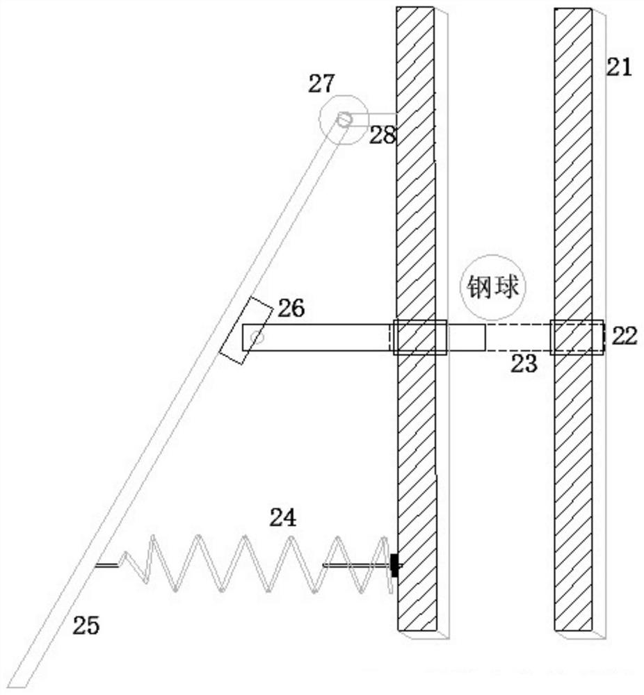
[0026] like figure 1 with Figure 4 As shown, the present invention is a gravity-displacement automatic energy storage power station, which includes a tower 2 built on a hillside 1, a load-bearing steel cable 4 on the tower 2, and a cable holder 36 fixed on the load-bearing steel cable 4. Ball lifting grid 3, the motor that drives the load-bearing steel cable 4 to move 5, the generator driven by the load-bearing steel cable 4 to generate electricity 6, the high-level storage court built at a high place 7, the low-level storage court for storing steel balls when the steel ball falls 8. Both the high storage court 7 and the low storage court 8 are equipped with a storage court unloading port 9 and a storage court lifting port 10. In order to realize the automatic delivery and homing of the gravity steel ball 12, the ground of the high ...


PUM


Abstract

The invention discloses a gravity steel ball displacement type automatic energy storage power station and a working method. The power station comprises gravity steel balls, a tower erected on a hillside, a ball lifting net rack, a bearing steel cable, a high-position ball storage field, a low-position ball storage field, a generator driven by a transmission system and the like. Based on the difference of peak-valley electricity prices, the gravity steel balls are lifted to the high-position ball storage field through the ball lifting net rack by utilizing electric energy at a low electricity price, the gravity steel balls fall down from the high position during the peak period of electricity utilization, the generator is driven to rotate to generate electric power when the steel balls fall down, the energy is converted between potential energy and electric energy of the gravity steel balls, and the purpose of storing abundant electric energy is achieved. Due to the fact that the steel balls are firm, reliable, stable in structure and free of weight loss during vertical conveying and storage, the energy conversion efficiency is much higher than that of water pumping energy storage, battery energy storage, compressed air energy storage, flywheel energy storage and electrolytic hydrogen production energy storage under construction at present, the construction cost and the site requirement are low, and the power station is suitable for industrial modular construction and operation and meets national energy storage requirements and national condition resources.

Description

technical field [0001] The invention relates to the field of energy storage technology, in particular to a gravity steel ball displacement automatic energy storage power station and a working method, which utilizes the peak-valley difference in electricity prices and uses electric energy to lift a large number of steel balls to a high-level storage field for storage when the electricity price is low. , during the peak period of electricity consumption, the gravity steel ball is delivered to the low storage field by reversing the ball lifting system to drive the generator to generate electricity. In mountainous and steep slope areas, this kind of energy storage power station with long span and large height difference can be built, which can cycle Production operation realizes the purpose of automatic energy storage. Background technique [0002] In recent years, clean energy such as wind energy and solar energy has developed rapidly. These energy companies are affected by nat...

Claims


Application Information

Patent Timeline
IPC IPC(8): H02J3/28H02J15/00
CPCH02J3/28H02J15/007Y02E60/16Y02E70/30Y02P80/10
Inventor 武忠全李俊菀龙国军童全峰
Owner XIAN THERMAL POWER RES INST CO LTD
Learn More