
Control circuit of vehicle-mounted charger of totem pole

An on-board charger and control circuit technology, which is applied in efficient vehicle charging, battery circuit devices, electric vehicle charging technology, etc. The effect of small dead time

Pending Publication Date: 2021-11-19
上海陆芯电子科技有限公司
View PDF0 Cites 0 Cited by
  • Summary
  • Abstract
  • Description
  • Claims
  • Application Information

AI Technical Summary

Problems solved by technology

When the totem pole bridgeless power factor correction circuit is working, the above devices will generate power loss, which makes the power consumption of the totem pole bridgeless power factor correction circuit relatively large
[0003] In addition, since the two switching tubes in the totem pole bridgeless power factor correction circuit are located on the same bridge arm, it is necessary to set a dead time to prevent a direct short circuit, and the topology can only work in the current discontinuous and critical conduction modes, and cannot work In the current continuous mode, there is no bridge on the totem pole at this time, and the two switching tubes work in the hard switching state at the same time, and the loss is large

Method used


Image

  • Control circuit of vehicle-mounted charger of totem pole
  • Control circuit of vehicle-mounted charger of totem pole
  • Control circuit of vehicle-mounted charger of totem pole

Examples


Embodiment Construction

[0029] The present invention will be further described in detail below in conjunction with the accompanying drawings and embodiments. It should be understood that the specific embodiments described here are only used to explain the present invention, but not to limit the present invention. In addition, it should be noted that, for the convenience of description, only some structures related to the present invention are shown in the drawings but not all structures.

[0030] Before discussing the exemplary embodiments in more detail, it should be mentioned that some exemplary embodiments are described as processes or methods depicted as flowcharts. Although the flowcharts describe the steps as sequential processing, many of the steps may be performed in parallel, concurrently, or simultaneously. Additionally, the order of steps may be rearranged. A process may be terminated when its operations are complete, but may also have additional steps not included in the figure. A proc...


PUM


Abstract

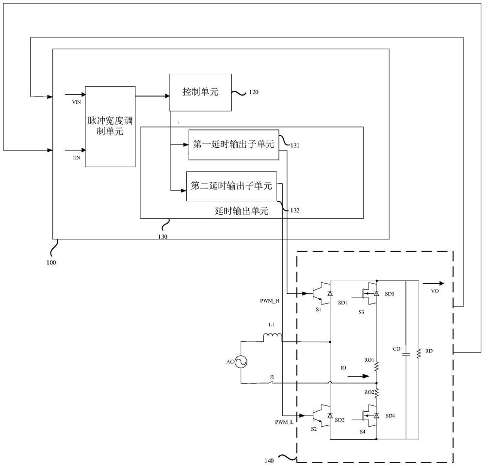
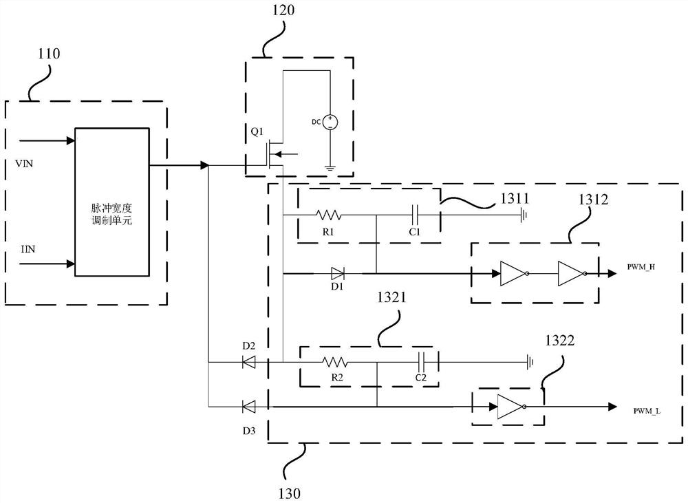
The invention discloses a control circuit of a vehicle-mounted charger of a totem pole. The control circuit comprises a totem pole power circuit and a PWM control circuit. The PWM control circuit comprises a pulse width modulation unit, a control unit and a delay output unit. The pulse width modulation unit is connected with the output end of the totem pole power circuit and is used for outputting a control signal according to the voltage and current output by the totem pole power circuit. The control unit is connected with the pulse width modulation unit and is used for outputting a PWM signal according to the control signal. The delay output unit is connected with the control unit and is used for delaying the PWM signal and then outputting the PWM signal. The control end of the totem pole power circuit is connected with the delay output unit and is used for controlling the working state of the totem pole power circuit according to the delayed PWM signal. According to the control circuit of the invention, the PWM signal is delayed through the delay output unit, the dead time of the totem pole power circuit can be reduced, and the overall efficiency and the power factor of the vehicle-mounted charger of the totem pole are improved.

Description

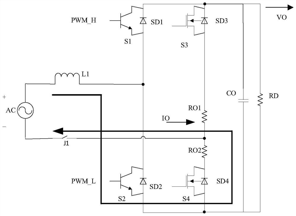
technical field [0001] Embodiments of the present invention relate to the technical field of electric vehicles, and in particular to a control circuit of a totem pole on-board charger. Background technique [0002] The controller (On-Board Controller, OBC) of the existing on-board charger includes a Totem-pole Bridgeless Power Factor Correction circuit (Totem-pole Bridgeless Power Factor Correction) and a power resonant circuit (Logical Link Control, LLC). , the totem pole bridgeless power factor correction circuit includes four switching tubes and four diodes, the first bridge arm is composed of two switching tubes and two diodes in series, and the second bridge arm is composed of two switching tubes and two diodes in series Composed of two diodes connected in series. When the totem pole bridgeless power factor correction circuit is working, the above-mentioned devices will generate power loss, so that the power consumption of the totem pole bridgeless power factor correct...

Claims


Application Information

Patent Timeline
Patent Type & Authority Applications(China)
IPC IPC(8): H02M1/42H02M1/38H02M7/219H02J7/02B60L53/24
CPCH02M1/4233H02M1/38H02M7/219H02J7/02B60L53/24Y02T10/70Y02T10/7072Y02T90/14Y02T10/92
Inventor 曾祥幼张杰胡舜涛
Owner 上海陆芯电子科技有限公司
Learn More