
Birotor micro-flow energy capturing power generation device based on piezoelectric effect
A piezoelectric effect, power generation device technology, applied in the field of dual-rotor micro-flow energy capture energy generation devices, can solve the problems of poor practicability of low-velocity micro-flow, reduce the minimum power generation flow rate, etc., to expand the flow rate capture range, increase the oscillation frequency, The effect of high energy density
- Summary
- Abstract
- Description
- Claims
- Application Information
AI Technical Summary
Problems solved by technology
Method used
Image

Examples
Embodiment Construction
[0031] The present invention will be further described below in conjunction with drawings and embodiments.
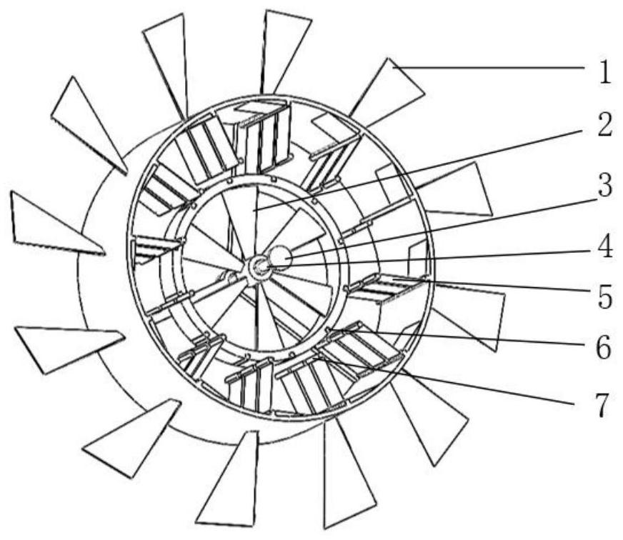
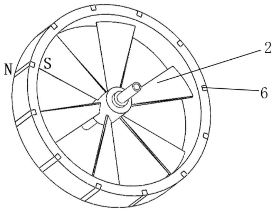
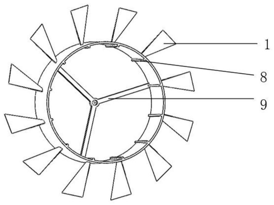
[0032] Such as figure 1 As shown, the specific implementation device includes an outer ring blade 1, an inner ring blade 2, a magnetic piezoelectric assembly and a magnetic steel 6; the inner ring blade 2 is movably fitted in the middle of the outer ring blade 1, and the inner ring blade 2 and The outer ring blades 1 are coaxially arranged and relatively rotated, and there is an annular gap between the inner ring blades 2 and the outer ring blades 1, and a plurality of sheet-shaped magnetic piezoelectric components and a plurality of magnetic steels 6 are arranged in the annular gap , a plurality of piezoelectric magnetic components are arranged at intervals along the circumferential direction of the annular gap, and the sheet-shaped outer sides of the plurality of piezoelectric magnetic components are fixedly connected to the inner peripheral surface of the outer ring ...
PUM
 Abstract
Description
Claims
Application Information