Building health state detection system and detection method thereof

A health status and detection system technology, applied to measuring devices, instruments, etc., can solve problems such as waste of human resources

Pending Publication Date: 2021-11-23
周文波
View PDF0 Cites 4 Cited by
  • Summary
  • Abstract
  • Description
  • Claims
  • Application Information

AI Technical Summary

Problems solved by technology

[0003] However, the completed building in the prior art is manually inspecting each tile and each self-built wall to determine the problems of the tiles and self-built walls; thereby causing a large amount of waste of human resources

Method used


Image

  • Building health state detection system and detection method thereof
  • Building health state detection system and detection method thereof
  • Building health state detection system and detection method thereof

Examples


Embodiment 1

[0107] refer to Figure 1-9 shown.

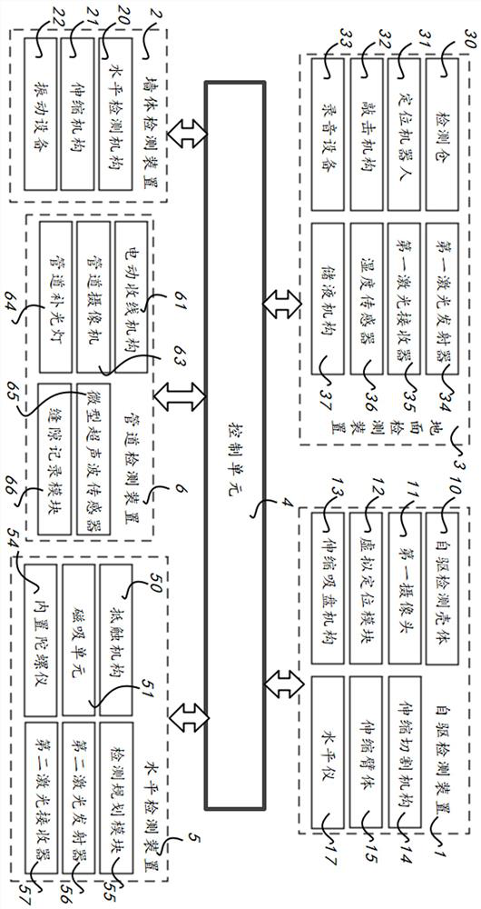
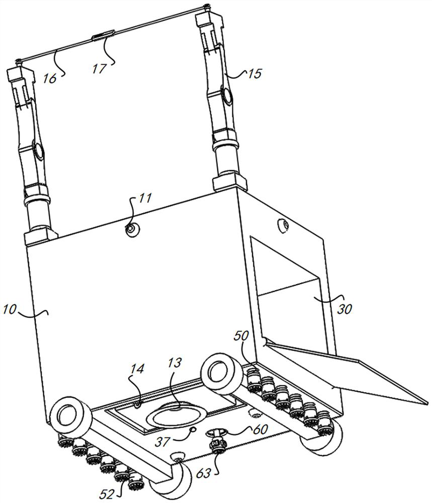
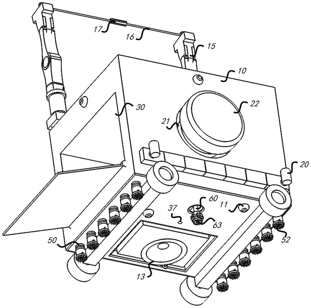
[0108] Specifically, this embodiment provides a building health status detection system, including: a self-driving detection device 11, which includes a self-driving detection housing 10, a first camera 11, a virtual positioning module 12, a telescopic suction cup mechanism 13, a telescopic cutting Mechanism 14, telescopic arm body 15, traction rope body 16 and spirit level 17; Wall body detection device 2, it comprises level detection mechanism 20, telescopic mechanism 21, vibration equipment 22 and conflicting layer; Ground detection device 3, it comprises detection bin 30 , a positioning robot 31, a knocking mechanism 32, a recording device 33, a first laser transmitter 34 and a first laser receiver 35; The detection device 3 is connected.

[0109] Wherein, the control unit 4 is also connected with the registered user terminal, the property management center of the area where the building is located, and the building management agency ...

Embodiment 2

[0146] refer to Figure 1-4 , Figure 7-12 shown.

[0147] This embodiment is an extension on the basis of Embodiment 1. Specifically, in this embodiment, a level detection device 5 is also included. The level detection device 5 includes a collision mechanism 50, a magnetic attraction unit 51, and an identification housing 52. The mechanism 50 is arranged at the bottom area of ​​the self-driving detection housing 10 and is respectively connected with the control unit 4 and the magnetic attraction unit 51; the magnetic attraction unit 51 is arranged at the front end of the collision mechanism 50 and is connected with the control unit 4; Below the magnetic attraction unit 51 .

[0148]Wherein, the interference mechanism 50 includes a third telescopic motor and a third telescopic rod, and the third telescopic rod driven and connected by the third telescopic motor stretches the magnetic unit 51; the magnetic unit 51 is connected with the third telescopic rod, On the magnetic id...

Embodiment 3

[0164] refer to Figure 1-3 , Figure 13-14 shown.

[0165] This embodiment is an extension of the basis of Embodiment 2. Specifically, in this embodiment, the ground detection device 3 also includes a buried detection strip 38, a humidity sensor 36, and a liquid storage mechanism 37. The buried detection strip 38 is embedded in the In the seam area between the bottoms of the floor tiles, the humidity sensor 36 is arranged at intervals on the upper surface of the buried detection strip 38 and wirelessly connected with the control unit 4; the liquid storage mechanism 37 is arranged at the bottom of the self-driving detection housing 10 and connected Unit 4 connection for dripping stored liquid into beautification areas between floor tiles.

[0166] Wherein, the number of the buried detection strips 38 is consistent with the number of seams of the floor tiles, and several humidity sensors 36 are arranged on the upper surface of the buried detection at even intervals to obtain ...


PUM


Abstract

The invention discloses a building health state detection system and a detection method thereof, and the system comprises a self-driven detection device which comprises a self-driven detection shell, a first camera, a virtual positioning module, a telescopic sucker mechanism, a telescopic cutting mechanism, a telescopic arm body, a traction rope body and a gradienter; a wall body detection device which comprises a horizontal detection mechanism, a telescopic mechanism, vibration equipment and an abutting layer; a ground detection device which comprises a detection bin, a positioning robot, a knocking mechanism, recording equipment, a first laser transmitter and a first laser receiver; a control unit which is respectively connected with the driving detection device, the wall body detection device and the ground detection device and is used for judging the hollowing problem of the house tiles by knocking the division positioning points of the house tiles; the structure level problem of the self-built wall of the house is detected by knocking the self-built wall of the house, so that the potential safety hazard of ceramic tiles of the self-built wall is reduced.

Description

technical field [0001] The invention relates to the field of building health detection, in particular to a building health state detection system and a detection method thereof. Background technique [0002] Urban buildings are becoming denser and higher, which is the trend of urban development. Due to various uncontrollable natural disasters or in the process of man-made construction, the interior decoration of the building is prone to problems such as fracture, displacement, and inclination. This problem is unpredictable and will bring immeasurable property losses to people, so the detection of the health status of buildings is very important, and the application of Internet of Things technology in building health detection is very important for mastering construction work. It is of great significance to detect the state of the building, detect structural damage in time, and evaluate the safety of the building. This is the health detection of the building. [0003] Howev...

Claims


Application Information

Patent Timeline
Patent Type & Authority Applications(China)
IPC IPC(8): G01D21/02
CPCG01D21/02
Inventor 周文波
Owner 周文波
Why Eureka
Try Eureka