Power conversion device and abnormality detection method

A technology of power conversion device and detector, which is applied in the direction of output power conversion device, measurement device, conversion equipment for intermediate conversion to direct current conversion, etc., and can solve problems such as damage and unstable operation of the system

Active Publication Date: 2021-11-23
HITACHI LTD
View PDF11 Cites 0 Cited by
  • Summary
  • Abstract
  • Description
  • Claims
  • Application Information

AI Technical Summary

Problems solved by technology

The DC voltage detector is necessary to control the DC voltage of the power conversion device, and the abnormality of the DC voltage detector will lead to unstable operation of the system. In the worst case, the system may stop unexpectedly and cause large damage.

Method used


Image

  • Power conversion device and abnormality detection method
  • Power conversion device and abnormality detection method
  • Power conversion device and abnormality detection method

Examples


no. 1 approach

[0147] use Figures 1 to 25F A power conversion system according to a first embodiment of the present invention will be described.

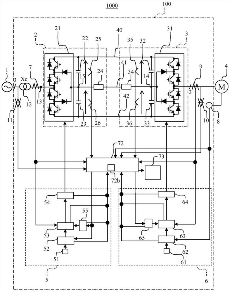
[0148] figure 1 It is an overall configuration diagram of the power conversion system of the first embodiment.

[0149] The power conversion system 1000 includes: an AC power source 1 that supplies AC power; a power conversion device 100 that converts the AC power supplied from the AC power source 1 into desired AC power and outputs it; The output AC power operates. The power conversion device 100 is connected to the electric motor 4 via, for example, an AC cable.

[0150] The power conversion device 100 has: a transformer 12 that transforms AC power; and a converter unit (also referred to as a converter) 2 that is interconnected with the AC power source 1 via the transformer 12 and converts the AC power from the AC power source 1 into DC power; an inverter unit (also referred to as an inverter) 3 that converts the DC power output from the co...

no. 2 approach

[0473] Next, use Figure 24A to Figure 25F A power conversion device according to a second embodiment will be described.

[0474] The power conversion device 100 of the power conversion system 1000 of the second embodiment has the same structure as the power conversion device 100 of the first embodiment.

[0475] The second embodiment differs from the first embodiment in that in the second embodiment, the comprehensive diagnosis index is a vector composed of a plurality of indexes. Figure 24A-Figure 24F expressed with Figure 21A-Figure 21D An example of setting the comprehensive diagnostic index as a vector under the same conditions. Figure 24A-Figure 24F The comprehensive diagnosis index in is a vector composed of two elements, the value of the index 203 and the value of the index 206 .

[0476] Figure 24A-Figure 24F is the case indicating that the DC voltage detector 26 is abnormal Figure 21A-Figure 21D A diagram showing an example of a case where the comprehensive...

no. 3 approach

[0483] Next, use Figure 26 to Figure 29D A power conversion device according to a third embodiment will be described.

[0484] The power conversion device 100 of the power conversion system 1000 of the third embodiment has the same structure as the power conversion device 100 of the first embodiment.

[0485] Figure 26 to Figure 27 Represents a flow chart, for and Figure 18 to Figure 19 The difference in the flow chart will be explained.

[0486] Figure 26 to Figure 27 Steps S201 to S205 and S207 to S213 in the Figure 18 to Figure 19 Steps S101 to S105 and steps S107 to S113 are the same.

[0487] Figure 26 Step S206 in and Figure 18 Step S106 in is different.

[0488] The difference from step S106 in the first embodiment is that in the first embodiment, K CP 、K CN 、K IP 、K IN is 0 or 1, in contrast, in the third embodiment, K CP 、K CN 、K IP 、K IN Take any value. Preferably, this arbitrary value is set to a value greater than 0 and less than 1.

[0489] ...


PUM


Abstract

The invention provides a power conversion device and an abnormality detection method. A power conversion device (100) is provided with: a first-type index calculation unit that calculates a first-type index for diagnosing the presence or absence of an abnormality in a DC voltage detector on the basis of an index using a detection value of the DC voltage detector; a second-type index calculation unit that calculates a second-type index that is represented as an index change when a detection abnormality in which a detection value changes in a predetermined direction occurs in either the first DC voltage detector (25) or the second DC voltage detector (26); an integrated diagnostic index calculation unit that calculates an integrated diagnostic index on the basis of the second type of index; and an abnormality determination unit (72) that performs, with respect to the DC voltage detectors, an operation of switching the detection value of the DC voltage detector assumed to be abnormal to an output estimated value estimated from the detection values of the other DC voltage detectors. On the basis of a change in the comprehensive diagnosis index, it is determined which of the first DC voltage detector and the second DC voltage detector has occurred an abnormality.

Description

technical field [0001] The present invention relates to a power conversion device and an abnormality detection method. Background technique [0002] There is known a power converter that converts power from an AC power source into power with variable voltage and variable frequency. In the power conversion device, a smoothing capacitor and a DC voltage detector for measuring the voltage across the smoothing capacitor are provided in the DC circuit, and the DC voltage is controlled to be constant by the power supply and reception of the AC system interconnected with the power converter. . [0003] For example, as a technique for checking the soundness of a DC voltage detector, a technique for determining abnormality from a plurality of signals during operation is known (see Patent Document 1). [0004] Patent Document 1 discloses a technique of creating a plurality of diagnostic indicators from the behavior of the DC voltage during operation in order to confirm the soundness...

Claims


Application Information

Patent Timeline
Patent Type & Authority Applications(China)
IPC IPC(8): H02M7/487H02M5/44G01R19/00
CPCH02M7/487H02M5/44G01R19/00
Inventor 田中秀明秋田佳稔景山宽伊藤智道
Owner HITACHI LTD
Why Eureka
Try Eureka