Double-arc curved surface harmonic drive speed reducer

A technology of harmonic drive and reducer, applied in the direction of transmission, transmission parts, belt/chain/gear, etc., can solve the problems of tooth root fracture, limited bearing capacity, easy stress concentration, etc., to extend service life, improve The effect of carrying capacity and improving transmission accuracy

Pending Publication Date: 2021-11-26
众合天成智能装备(廊坊)有限公司
View PDF0 Cites 0 Cited by
  • Summary
  • Abstract
  • Description
  • Claims
  • Application Information

AI Technical Summary

Problems solved by technology

[0003] The reduction ratio of the harmonic transmission reducer is usually between 50-300 in the single-stage reduction, and the reduction ratio in the double-stage reduction is between 1000-50000. Due to the restriction of the transmission principle of the fatigue strength machine, it cannot meet the customer's requirements for harmonics. The speed ratio of the transmission reducer needs to be between 300-900, which limits the application range of the harmonic drive reducer
[0004] The flexspline of the harmonic transmission reducer is mainly affected by the joint action of bending alternating stress and torsional shear stress. The existing involute tooth profile is in the transmission, and the intersection of the tooth top and the tooth profile is a sharp angle. In the process of meshing in and out with the rigid wheel teeth, it is easy to produce tooth profile interference and addendum interference, resulting in noise; the flexible wheel is a thin-walled part, and the involute tooth root transition fillet is small, which is easy to stress concentration , resulting in tooth root fracture and limited load-carrying capacity

Method used


Image

  • Double-arc curved surface harmonic drive speed reducer
  • Double-arc curved surface harmonic drive speed reducer
  • Double-arc curved surface harmonic drive speed reducer

Examples


Embodiment Construction

[0030] The following is attached Figure 1-3 The application is described in further detail.

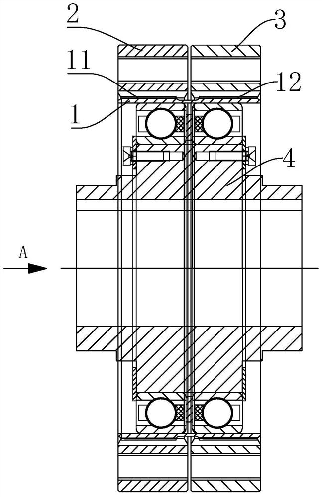
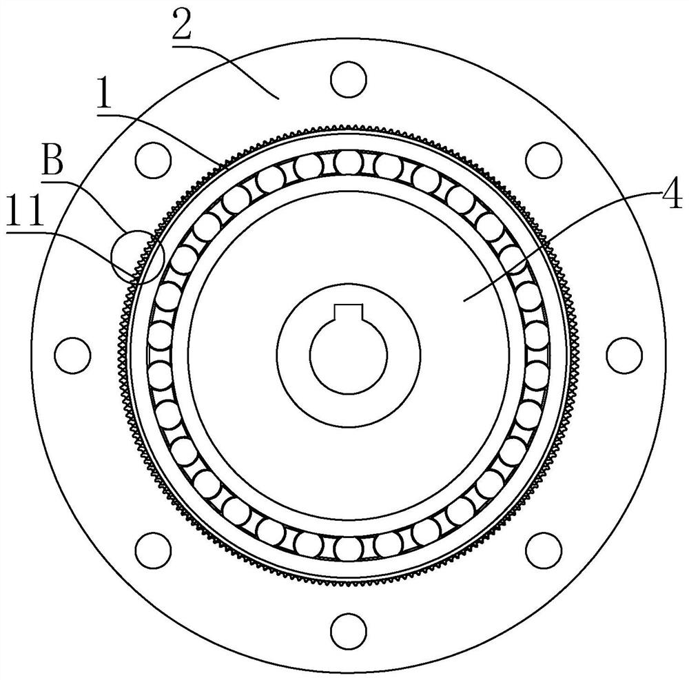
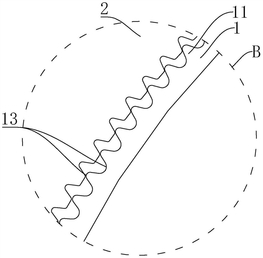
[0031] Such as figure 1 As shown, a double-arc surface harmonic drive reducer of the present application includes a flexspline 1, an input steel pulley 2, an output steel pulley 3 and a wave generator 4. The wave generator 4 is arranged inside the flexspline 1, and the flexspline 1 adopts a double-arc curved tooth profile, and the outer side of the flexspline 1 is provided with external teeth. The external teeth of the flexspline 1 include coaxial first-stage external teeth 11 and second-stage external teeth 12. The first-stage external teeth 11 and the second-stage external teeth The second-stage external teeth 12 are respectively located on both sides of the flexspline 1, the first-stage external teeth 11 of the flexspline 1 mesh with the internal teeth of the input steel wheel 2, the second-stage external teeth 12 of the flexspline 1 and the output steel wheel 3 The internal tee...


PUM


Abstract

The invention relates to the technical field of speed reducers, and discloses a double-arc curved surface harmonic drive speed reducer. The speed reducer comprises a flexible gear, an input steel gear, an output steel gear and a wave generator; the wave generator is arranged on the inner side of the flexible gear, outer teeth are arranged on the outer side of the flexible gear with a double-arc curved surface tooth profile, the outer teeth of the flexible gear comprise first-stage outer teeth and second-stage outer teeth, the first-stage outer teeth and the second-stage outer teeth are located on the two sides of the outer wall of the flexible gear respectively, the first-stage outer teeth mesh with inner teeth of the steel gear, the second-stage outer teeth mesh with inner teeth of the output steel gear, the wave generator is fixedly connected with an output shaft of a motor, the input steel gear is fixedly connected to a machine base of the double-arc curved surface harmonic drive speed reducer, and the output steel gear is fixedly connected with the output shaft; the first-stage outer teeth and the second-stage outer teeth are different in tooth number and modulus and are distributed on the same reference circle. The speed ratio can range from 300 to 900, the working noise is low, and the bearing capacity is high.

Description

technical field [0001] The present application relates to the technical field of reducers, in particular to a double-arc harmonic drive reducer. Background technique [0002] Harmonic drive reducer transmission technology and transmission devices have been widely used in many fields. The core components of the harmonic drive reducer are the flex spline, the rigid spline and the wave generator. Engagement; the teeth of the flexible spline and the rigid spline at both ends of the short axis are completely disengaged; in the interval between the major axis and the short axis of the wave generator, the teeth of the flexible spline and the rigid spline are in a half meshing state; Others gradually withdraw from engagement and are in a half-disengaged state. [0003] The reduction ratio of the harmonic transmission reducer is usually between 50-300 in the single-stage reduction, and the reduction ratio in the double-stage reduction is between 1000-50000. Due to the restriction o...

Claims


Application Information

Patent Timeline
IPC IPC(8): F16H49/00F16H57/023F16H57/028
CPCF16H49/001F16H57/023F16H57/028
Inventor 侯国兴王伟
Owner 众合天成智能装备(廊坊)有限公司
Why Eureka
Try Eureka