
Large-area-array compact medium-wave infrared circumferential scanning optical device and system

An optical device and a compact technology, which is applied in the field of medium-wave infrared scanning optical system, can solve the problems of difficult to meet the system performance requirements, low sensitivity, short detection distance, etc., and achieve the effect of compact structure, improved sensitivity, and long focal length

Active Publication Date: 2021-11-26
西安中科立德红外科技有限公司
View PDF4 Cites 0 Cited by
  • Summary
  • Abstract
  • Description
  • Claims
  • Application Information

AI Technical Summary

Problems solved by technology

[0004] The purpose of the present invention is to solve the technical problems of short detection distance and low sensitivity in the existing infrared scanning system, and it is difficult to meet the higher performance requirements of the system, and to provide a large area array compact mid-wave infrared scanning optical device and system

Method used


Image

  • Large-area-array compact medium-wave infrared circumferential scanning optical device and system
  • Large-area-array compact medium-wave infrared circumferential scanning optical device and system
  • Large-area-array compact medium-wave infrared circumferential scanning optical device and system

Examples


Embodiment Construction

[0038] The present invention will be further described below in conjunction with the accompanying drawings and embodiments.

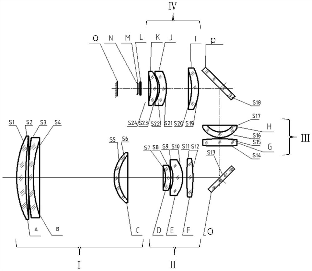
[0039] A large area array compact mid-wave infrared circular scanning optical device, which is provided with four sets of lenses and other components in sequence from the object side to the image side, specifically including the front fixed group I with positive refractive power arranged along the optical path, Telephoto rear fixed group II with positive refractive power, swing compensating mirror O, secondary imaging front fixed group III with positive refractive power, mirror P, secondary imaging rear fixed group IV with positive refractive power, protection window L, filter M and cold diaphragm N.

[0040] The telescopic front fixed group I includes a meniscus silicon positive lens A with a convex surface facing the object side, a meniscus germanium negative lens B with a convex surface facing the object side, and a meniscus germanium positive lens w...


PUM


Abstract

The invention relates to a large-area-array compact medium-wave infrared circumferential scanning optical device and system, and aims to solve the problems that an infrared circumferential scanning system is short in detection distance, low in sensitivity and difficult to meet the requirement for higher performance of the system. The device comprises a telescope front fixing group I with positive focal power, a telescope rear fixing group II with positive focal power, a swing scanning compensating mirror O, a secondary imaging front fixing group III with positive focal power, a reflecting mirror P, a secondary imaging rear fixing group IV with positive focal power, a protection window L, an optical filter M and a cold diaphragm N which are sequentially arranged along an optical path from an object space to an image space. The telescope rear fixing group II and the telescope front fixing group I form a telescope group; the secondary imaging rear fixing group IV and the secondary imaging front fixing group III form a secondary imaging lens group; the exit pupil of the telescope group and the entrance pupil of the secondary imaging lens group coincide, the sweep compensation lens O is located at the coincidence position, the sweep compensation lens O and the reflector P turn a light path by 180 degrees to form a U-shaped light path, and the U-shaped light path and the staring type focal plane medium wave refrigeration detector form the system.

Description

technical field [0001] The invention relates to a medium-wave infrared circular scanning optical system, in particular to a large-area compact medium-wave infrared circular scanning optical device and system, which can be mounted on search and tracking equipment such as theodolites and turntables, and is mainly used for warning and searching , tracking and measuring, etc. Background technique [0002] In recent years, infrared thermal imaging systems have been widely used in military and security, and related technologies have also developed rapidly. Because the surrounding scanning system has the functions of large field of view fast scanning and searching and small field of view tracking, it can realize all-weather real-time alert. [0003] The weekly scanning system for infrared warning applications requires a larger field of view and a longer focal length to meet a wider search range and higher resolution. At the same time, it needs to solve the problem of rapid rotatio...

Claims


Application Information

Patent Timeline
Patent Type & Authority Applications(China)
IPC IPC(8): G02B13/02G02B13/00G02B1/02G02B26/10G01J5/00G01J5/08
CPCG02B13/02G02B13/0045G02B13/0065G02B13/008G02B1/02G02B26/105G01J5/00G01J5/0806G01J5/0803G01J2005/0077Y02A90/10
Inventor 刘伟焦洋洋王鹏郭得福段程鹏
Owner 西安中科立德红外科技有限公司
Learn More