Handheld laser welding deviation rectifying device

A laser welding and deflection correction device technology, which is applied to laser welding equipment, auxiliary equipment, welding equipment, etc., can solve the problems of unfavorable long-term observation of weld seams, welding, and small spot size, so as to achieve safe and reliable welding work and reduce fire hazards Possibility, quality improvement effect

Pending Publication Date: 2021-11-30
王秋
View PDF7 Cites 0 Cited by
  • Summary
  • Abstract
  • Description
  • Claims
  • Application Information

AI Technical Summary

Problems solved by technology

Laser welding has high requirements for the weld seam gap, requires high assembly accuracy of the weldment, and requires that the position of the beam on the workpiece cannot be significantly shifted. This is because the spot size of the laser is small after focusing and the weld seam is narrow. For the filler metal material, If the assembly accuracy of the workpiece or the positioning accuracy of the beam does not meet the requirements, it is easy to cause welding defects
[0003] When existing welders perform laser welding on pipe fittings, the welders use their eyes to observe the gap. In the strong arc light, it is not conducive to observe the weld seam for a long time, and the beam of laser welding is prone to shift, resulting in welding defects. Therefore, we Proposed a hand-held laser welding deviation correction device

Method used


Image

  • Handheld laser welding deviation rectifying device
  • Handheld laser welding deviation rectifying device
  • Handheld laser welding deviation rectifying device

Examples


Embodiment Construction

[0025] The following will clearly and completely describe the technical solutions in the embodiments of the present invention with reference to the accompanying drawings in the embodiments of the present invention. Obviously, the described embodiments are only some, not all, embodiments of the present invention.

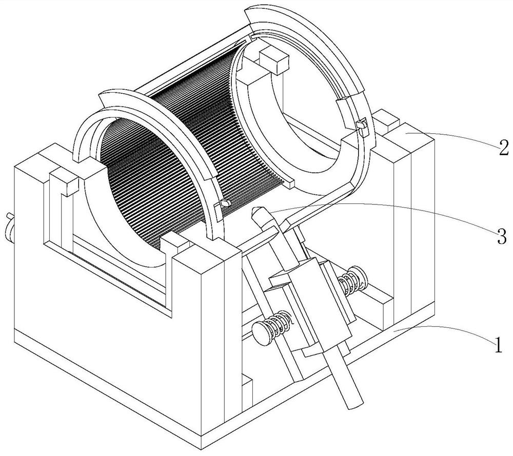
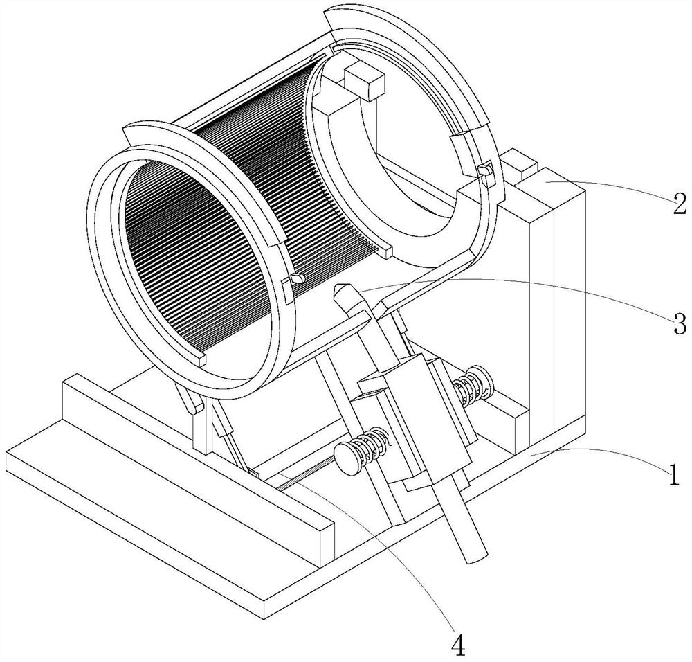
[0026] see Figure 1-6 , the present invention provides a technical solution: a hand-held laser welding deviation correction device, including a device base 1 and a fixing device 2, there are two fixing devices 2, and the two fixing devices 2 are respectively embedded and fixed on the top left side of the device base 1 and On the right side, a deviation correction mechanism 3 for correcting the deviation of the laser welding of pipe fittings is arranged between the two fixing devices 2 , and a cleaning mechanism 4 for cleaning the device base 1 is arranged below the deviation correction mechanism 3 .

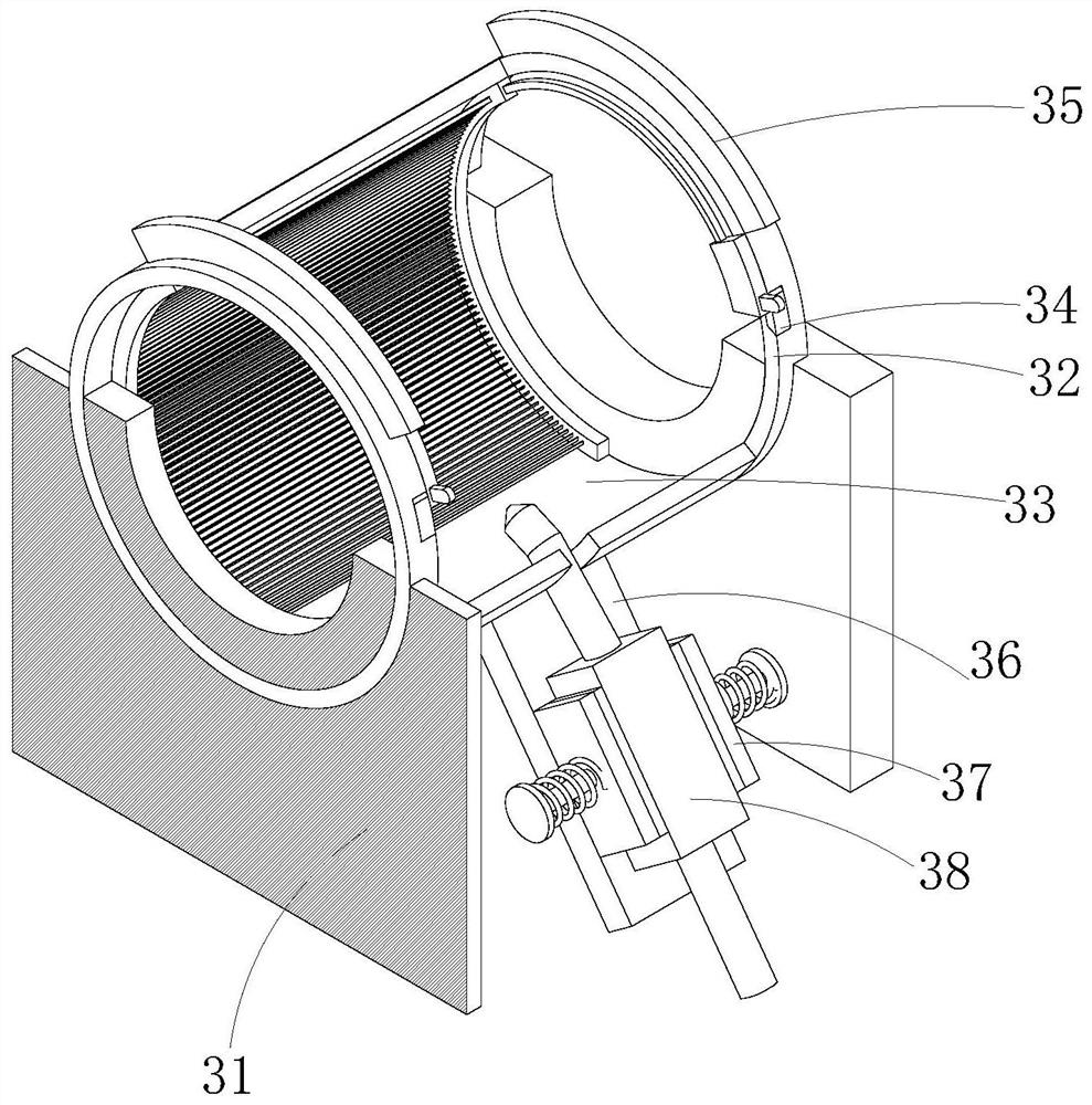
[0027] Such as image 3 As shown, the deviation correction mecha...


PUM


Abstract

The invention discloses a handheld laser welding deviation rectifying device, and relates to the technical field of welding equipment. The device comprises a device base and two fixing devices, wherein the two fixing devices are fixedly embedded in the left side and the right side of the top of the device base separately; a deviation rectifying mechanism used for conducting laser welding deviation rectifying on pipe fittings is arranged between the two fixing devices; a cleaning mechanism used for cleaning the device base is arranged below the deviation rectifying mechanism; and the deviation rectifying mechanism comprises a circular groove plate and a handheld laser welding main body. A connecting plate is matched with a semicircular guard plate, and the connecting plate is rotated anticlockwise to drive the semicircular guard plate to rotate anticlockwise, so that the connecting plate drives a handheld laser welding main body to conduct annular laser welding on the pipe fittings, and the situation that when a welder conducts laser welding on the pipe fittings, a laser welding light beam is prone to deviation to cause a welding defect is avoided. Therefore, the laser welding quality of the pipe fittings is improved.

Description

technical field [0001] The invention relates to the technical field of welding equipment, in particular to a hand-held laser welding deviation correction device. Background technique [0002] Laser welding is an efficient and precise welding method that uses a high-energy-density laser beam as a heat source. Laser welding is one of the important aspects of the application of laser material processing technology. Laser welding has high requirements for the weld seam gap, requires high assembly accuracy of the weldment, and requires that the position of the beam on the workpiece cannot be significantly shifted. This is because the spot size of the laser is small after focusing and the weld seam is narrow. For the filler metal material, If the assembly accuracy of the workpiece or the positioning accuracy of the beam cannot meet the requirements, it is easy to cause welding defects. [0003] When existing welders perform laser welding on pipe fittings, the welders use their e...

Claims


Application Information

Patent Timeline
IPC IPC(8): B23K26/282B23K26/70B23K37/053B23K26/08B23K26/16B08B1/00B23K101/06
CPCB23K26/282B23K26/702B23K37/0533B23K26/0876B23K26/16B23K2101/06B08B1/12
Inventor 王秋
Owner 王秋
Why Eureka
Try Eureka