Municipal sewage treatment device and method
A treatment device and municipal sewage technology, applied in water/sewage treatment, illuminated water/sewage treatment, oxidized water/sewage treatment, etc., can solve the problem that the quality of sewage treatment cannot meet the requirements well, the oxidation and decomposition of organic matter is not sufficient, Lack of high-quality disinfection treatment and other issues to achieve better treatment effect, lower treatment cost and strong applicability
- Summary
- Abstract
- Description
- Claims
- Application Information
AI Technical Summary
Problems solved by technology
Method used
Image

Examples
Embodiment 1
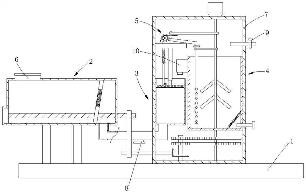
[0039] see Figure 1-6 , the present invention provides a technical solution: a municipal sewage treatment device, including a base 1, a pre-filter mechanism 2, a secondary filter mechanism 3, a stirring mechanism 4 and a mechanical pumping mechanism 5, and the pre-filter mechanism 2 includes a support rod 201 , settling box 202, screw mandrel 203, moving plate 204, first filter screen 205 and slag discharge pipe 206, support bar 201 is affixed to the left end of base 1 top, settling box 202 is affixed to the top of support bar 201, screw mandrel 203 is rotatably connected to the inner cavity of the settling tank 202, the moving plate 204 is screwed on the screw rod 203, and the moving plate 204 is installed obliquely, the first filter screen 205 is embedded on the moving plate 204, and the slag discharge pipe 206 is connected to the settling tank On the left side of 202, the top of the settling tank 202 is also provided with a water inlet 6.
[0040] Wherein, the secondary f...
Embodiment 2
[0045] Compared with embodiment 1, its difference is:
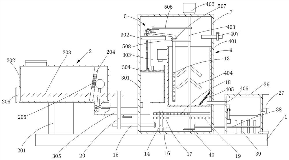
[0046] Wherein, the inner cavity of the connecting pipe 305 is also provided with a vibration mechanism near the settling tank 202. The vibration mechanism includes a cross bar 21, a rotating rod 22, a large connection ball 23, a small connection ball 24 and a vibrator 25, and the cross bar 21 is fixed horizontally. In the inner cavity of the connecting pipe 305, the rotating rod 22 is hinged on the cross bar 21, the large connecting ball 23 is installed on the end of the rotating rod 22 close to the first filter screen 205, and the small connecting ball 24 is affixed to the other end of the rotating rod 403. The vibrator 25 is installed on the inner wall of the connecting pipe 305 near the left side of the small connecting ball 24. The vibrator 25 adopts a common waterproof model, and the vibrator 15 is in an open state. When the moving plate 204 is separated from the large connecting ball 23, The vibrator 15 can also dr...
Embodiment 3
[0048] Compared with embodiment 1, its difference is:
[0049] Wherein, the base 1 top is also provided with a disinfection box 26, and the disinfection box 26 is communicated with the first drain pipe 406, the left side of the disinfection box 26 is provided with a liquid storage tank 27, and the bottom of the liquid storage tank 27 is provided with a liquid discharge pipe 28, And drain pipe 28 is communicated with sterilizing box 26, and the top of sterilizing box 26 inner chambers is provided with sterilizing lamp 29, and the right side of sterilizing box 26 is provided with second drainage pipe 30, the sewage is sterilized by the setting of sterilizing box, and storage An appropriate amount of disinfectant is stored in the liquid tank 27 .
PUM
 Abstract
Description
Claims
Application Information
 - Generate Ideas
- Intellectual Property
- Life Sciences
- Materials
- Tech Scout
- Unparalleled Data Quality
- Higher Quality Content
- 60% Fewer Hallucinations
Browse by: Latest US Patents, China's latest patents, Technical Efficacy Thesaurus, Application Domain, Technology Topic, Popular Technical Reports.
© 2025 PatSnap. All rights reserved.Legal|Privacy policy|Modern Slavery Act Transparency Statement|Sitemap|About US| Contact US: help@patsnap.com