
Leakage-proof and sand-blocking-proof drainage gas recovery plunger for high-inclination and sand-containing gas well

A technology of water drainage and gas recovery and large slope, applied in the field of tools, can solve problems such as inflexibility of single-section plunger, failure of spring plunger, and blockage at bends, etc., to achieve liquid sealing effect, reduce impact, and prevent liquid leakage Effect

Pending Publication Date: 2021-11-30
SOUTHWEST PETROLEUM UNIV
View PDF2 Cites 0 Cited by
  • Summary
  • Abstract
  • Description
  • Claims
  • Application Information

AI Technical Summary

Problems solved by technology

[0004] The purpose of the present invention is to solve the problems of inflexible single-section plunger and easy blockage and serious leakage at the bend in the case of high-inclination and sand-bearing gas wells
In the process of wellbore flow, debris is easy to deposit at the groove of the plunger and the connection spring, resulting in the failure of the spring plunger, frequent replacement, and longer construction period.

Method used


Image

  • Leakage-proof and sand-blocking-proof drainage gas recovery plunger for high-inclination and sand-containing gas well
  • Leakage-proof and sand-blocking-proof drainage gas recovery plunger for high-inclination and sand-containing gas well
  • Leakage-proof and sand-blocking-proof drainage gas recovery plunger for high-inclination and sand-containing gas well

Examples


Embodiment Construction

[0036] The present invention will be further described below in conjunction with the accompanying drawings and embodiments. It should be noted that, in the case of no conflict, the embodiments in the present application and the technical features in the embodiments can be combined with each other. It should be noted that, unless otherwise specified, all technical and scientific terms used in this application have the same meaning as commonly understood by those of ordinary skill in the art to which this application belongs. The disclosure of the present invention uses "comprises" or "comprises" and other similar words to mean that the elements or objects appearing before the words include the elements or objects listed after the words and their equivalents, without excluding other elements or objects.

[0037] In the present invention, the terms "first", "second" and the like are used to distinguish similar objects, rather than to describe a specific order or sequence, unless ...


PUM


Abstract

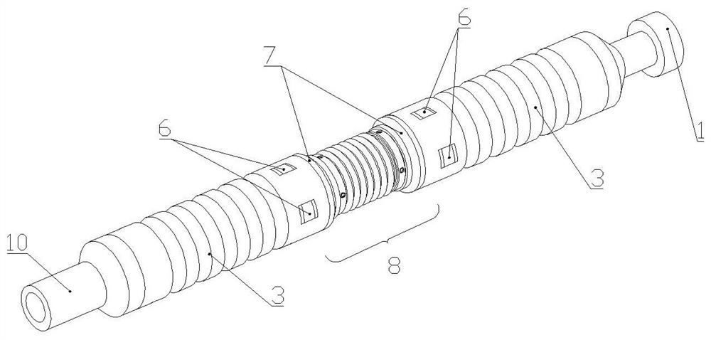
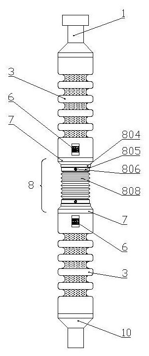
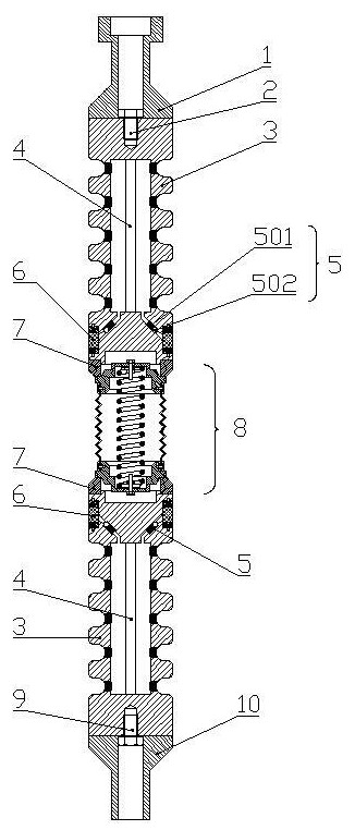
The invention discloses a leakage-proof and sand-blocking-proof drainage gas recovery plunger for a high-inclination and sand-containing gas well, and relates to the field of gas well drainage gas recovery. The leakage-proof and sand-blocking-proof drainage gas recovery plunger comprises a fishing head, a plunger body, an air bag, a one-way valve, an embedded sand-proof block, an elastic leakage-proof ring, an elastic connecting section and other components. In the descending process of the plunger body, the internal air bag shrinks and deforms, accumulated water at the bottom of the well enters a hollow area in the plunger body, and temporary storage of water is achieved; in the ascending process of the plunger body, the internal air bag expands and deforms, the temporarily stored water is ejected out of capillary perforations of the plunger body, a moving liquid film is formed outside the plunger body, and liquid sealing is achieved; meanwhile, the situation that gravel deposits and solidifies at the sunken position of the plunger body is avoided; the elastic leakage-proof ring and a corrugated pipe are pressed and expand at the bent position, the annular area is reduced, and physical leakage prevention is achieved; double leakage-proof measures are achieved, the connecting position of the plunger body is connected through the corrugated pipe and a spring, and the flexibility degree of the plunger body passing through the bent position is improved; and meanwhile, the corrugated pipe protects the spring against sand blocking, the drainage efficiency is improved, and good application prospects are achieved.

Description

technical field [0001] The invention relates to the field of gas well drainage and gas recovery, in particular to a method for reducing liquid leakage when the plunger is lifted, depositing and solidifying sand and gravel on the surface of the plunger, and improving the efficiency of the plunger drainage and gas recovery in the case of a highly inclined gas well with severe leakage. tools. Background technique [0002] The plunger gas lift process is widely used in drainage gas recovery, which has the advantages of high efficiency, economy and environmental protection. At present, most gas-lift plungers are single-section plungers, which are not strong in sealing and leakage prevention, and have low applicability to highly deviated wells, and are prone to sand sticking and corrosion, resulting in increased wellbore friction and replacement of plunger damage Frequent problems, such as patent publication number CN106014346A, although the plunger gas lift can solve the problem...

Claims


Application Information

Patent Timeline
IPC IPC(8): E21B43/12E21B37/00
CPCE21B43/122E21B43/123E21B37/00
Inventor 钟海全郑传根程长坤李志伟杜竟许鸷宇赵利康赵玉陈君
Owner SOUTHWEST PETROLEUM UNIV
Learn More